Loading...
Loading...
Loading...
Loading...
Loading...
Loading...
Loading...
Loading...
Loading...
Loading...
Loading...
Loading...
Loading...
Loading...
Loading...
Loading...
Loading...
Loading...
Loading...
Loading...
Loading...
Loading...
Loading...
Loading...
Loading...
Loading...
Loading...
Loading...
Loading...
Loading...
Loading...
Loading...
Loading...
Loading...
Loading...
Loading...
Loading...
Loading...
Loading...
Loading...
Loading...
Loading...
Loading...
Loading...
Loading...
Loading...
Loading...
Loading...
Loading...
Loading...
Loading...
Loading...
Loading...
Loading...
Loading...
Loading...
Loading...
Loading...
Loading...
Loading...
Loading...
Loading...
Loading...
Loading...
Loading...
Loading...
Loading...
Loading...
Loading...
Loading...
Loading...
Loading...
Loading...
Loading...
Loading...
Loading...
Loading...
Loading...
Loading...
Loading...
Loading...
Loading...
Loading...
Loading...
Loading...
Loading...
Loading...
Loading...
Loading...
Loading...
Loading...
Loading...
Loading...
Theia3D is the premier solution for accurate, reliable, and generalizable markerless motion capture. With our software at your fingertips, you'll unlock the power to analyze human movement like never before. Whether you're a researcher exploring human movement, a sports biomechanist tasked with unleashing athletes' full potential, or a product developer working on the next generation of athletic equipment, Theia3D empowers you to:
Obtain motion data without the need for suits, sensors, or markers.
Transform raw video footage into precise, 3D models of human movement.
Integrate effortlessly with leading motion capture software.
Dive into the future of motion capture and elevate your project to new heights.
This online resource acts as a one-stop shop for almost any question related to using and getting the most from Theia3D. Visiting for the first time? Check out the and sections. Looking for details on a specific setting or tool? Look under the section header corresponding to the relevant dropdown menu from the software.
Still looking for more information or find something that's missing? We'd love to hear from you directly! Please email or .
New users should start at the guide. This guide contains tutorials that introduce you to the software interface and walk you through the most common workflows - such as calibration and analysis - so that you can harness the power of Theia3D for yourself.
The reference guides contain detailed information about the interface, settings, and tools available in Theia3D. They are excellent resources for advanced users looking to fine-tune workflows and optimize Theia3D for their specific use cases.
For any questions and issues, please reach out to .
Clear Workspace
Ctrl + F4
Load Video Data
Ctrl + O
Load Calibration File
Ctrl + Shift + O
Save Workspace
Ctrl + S
Save Skeleton Poses
Ctrl + Shift + S, 1
Save Video Overlay
Ctrl + Shift + S, 2
Save Individual 2D view overlays
Ctrl + right-click on the 2D view
Save Grid of all 2D view overlays
Ctrl + Shift + right-click on the 2D view
Save 3D View
Ctrl + right-click on the 3D viewer area
Run Analysis
Ctrl + F
Theia3D is an advanced deep learning algorithm-based software which runs and processes data on your local PC. This means that there are specific requirements in order for it to operate properly and perform as intended, which are laid out below.
Although there are laptops available which meet the system requirements and can run Theia software, we generally do not recommend laptops for dedicated processing of markerless data. Their reduced capabilities result in longer processing times, so it is recommended to use a dedicated desktop PC for data processing.
One or more CUDA-capable NVIDIA graphics card(s) with the following:
At least 8 GB of memory
Support for
Updated . The program will not run if the graphics driver is not up to date.
Recommended: octa-core i9 processor or better.
Recommended: 32 GB or greater.
Extrinsic chessboard calibration trials are used to determine the position and orientation of every camera in your camera system relative to your desired global coordinate system. As with lens calibration trials, users with wand calibration-capable systems (e.g. Qualisys Miqus, Vicon Vue or FLIR Blackfly S systems) are not required to complete chessboard calibration. A minimum of one chessboard calibration trial should be collected every time you set up your camera system, but collecting multiple is recommended. A new calibration is required any time a camera is moved, so having multiple calibration trials collected throughout a long data collection session can help prevent data loss due to accidental or unnoticed camera movements.
Chessboard calibrations must be performed at the resolution that will be used to record your movement data. If you will be using more than one resolution during your data collection, you must record chessboard calibration trials at each resolution.
Record chessboard calibration trials at a relatively low frame rate (20-30 Hz) to reduce file size and processing time.
Keep the chessboard as flat as possible during the calibration trial.
Focus on achieving groupings of 3+ cameras that can see the chessboard at all times.
Align the chessboard with marks on the ground so you can confirm that the global coordinate system is positioned correctly when processing movement trials.
Set up your camera system as desired for your data collection, following the recommendations in .
Choose or place visible marks on the ground which will be aligned with the global coordinate system, for confirmation when processing data.
Check that the chessboard is fully visible in at least 3 camera views when it is placed at the desired global coordinate system origin position.
Begin the recording.
To process extrinsic chessboard calibrations, see .
Extrinsic object calibration trials are used to determine the position and orientation of every camera in your system relative to the desired global coordinate system. Extrinsic object calibration uses the static position of a calibration object with known dimensions or known positions of specific key points on the object. These 3D dimensions or positions must be measured with high precision. The calibration object should be sufficiently large or the calibration key points should be spaced far apart within the capture volume and most points should be visible in every camera view. The key points can be coplanar or can vary in all three global dimensions.
A calibration object file must be created for your calibration object, containing 3D coordinates of the object key points. Each line of the file must contain three comma-separated values representing the global x-, y-, and z-coordinates of the key point, in millimeters. Each key point should be on its own line.
Object calibrations must be performed at the resolution that will be used to record your movement data. If you will be using more than one resolution during your data collection, you must record object calibration trials at each resolution.
Theia3D is a markerless motion capture solution that utilizes synchronized video data to produce accurate and reliable 3D pose estimates of humans visible within the video data. It leverages deep learning algorithms trained to identify humans and accurately predict the 2D positions of 124 keypoints on the human body, in every video frame of every camera. By fitting a scaled subject-specific inverse kinematic model to the keypoint predictions, the human’s pose is reconstructed in 3D and tracked throughout their movement. This data-driven approach results in a robust solution that is generalizable across environments and movements, allowing the accessible collection of high quality 3D motion capture data where it was previously impossible.
Here, we describe the basic framework for collecting markerless motion capture data using Theia3D; for more detailed instructions, please refer to the appropriate section of this documentation and any accompanying videos.
The following guidelines describe data collection best practices, but are not exhaustive. You may obtain high quality markerless motion capture data under different conditions from those described below.
Camera system setups differ from location to location, and may be subject to challenging data collection environment constraints. General recommendations for setting up your camera system include:
Most of the Display options shown here can also be toggled ON and OFF using the Display toggle buttons in the sidebar.
Show/Hide 3D View
Toggle showing the 3D View in the application. If toggled ON but the 3D View is not visible, drag the 3D View open from the right border of the application window.
Pose (.c3d) files can be saved and used to perform post-processing analysis steps in Visual3D software. Use the Save Skeleton Poses button to save skeleton pose .c3d files, or navigate to Save Skeleton Poses under the . Saved pose .c3d files can be opened in Visual3D, and a subject-specific model will automatically be applied to the Theia3D data in Visual3D without requiring the model to be defined.
The movement of each tracked individual is conveyed within the .c3d file using ROTATION signals, which are 4x4 pose (position and orientation) matrices for each segment’s local segment coordinate system, for every frame of data. A description of the is available from Visual3D documentation. Raw tracked landmarks are not included as signals in any output files from Theia3D.
A workspace folder contains the video and data files of a saved workspace. The video files are named according to their unique camera ID. The .t3d and .p3d files contain the analysis results. It is important that the contents of the workspace folder are not modified, including moving files in or out of the folder.
Theia3D workspaces can be used to save data at various stages of analysis, but are most useful for saving analyzed data that will be reviewed later. When a fully analyzed movement trial is saved as a Theia3D workspace, the saved data includes the 2D videos, calibration file, and all data associated with the analysis. Therefore, when a saved workspace is loaded, you can immediately review the analyzed data in the 2D and 3D viewers.
To open a Theia3D workspace while Theia3D is open, use and select the folder containing the workspace files.
Top open a Theia3D workspace while Theia3D is closed, you can double-click on the results.p3d file.
This error message arises when the chessboard calibration trial does not contain sufficient frames of overlapping visibility of the chessboard in 3 or cameras throughout the trial. This prevents the camera system from being properly calibrated, as there is insufficient information to calculate the position and orientation of all cameras in the system in 3D space.
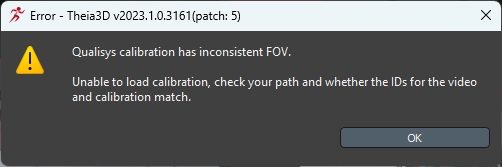
This error message arises when loading a calibration file. It indicates that the selected calibration file does not contain the required calibration parameters to calibrate the camera system of the loaded videos. The calibration file may be missing intrinsic parameters, extrinsic parameters, or a combination of both, which prevent it from calibrating the camera system for the video data.
The two prerequisites for batch processing of video data is that the videos are organized in the required nested folder structure as described in and that every trial has an assigned calibration file. Therefore, the and tools are included for use in TMBatch.
The Open into options allow you to easily open the currently selected batch processing directory, in either Windows Explorer or the command line.
One of the benefits offered by Theia3D markerless motion capture is automated tracking, which allows it to analyze large datasets without human intervention or supervision. This is achieved using the Theia3D Batch companion application to Theia3D, which allows a list of trials to be curated and batch analyzed sequentially. While batch processing is efficient and does not require supervision, we always recommend that you manually examine and check the quality of your markerless data and calibrations using Theia3D, before setting up a batch analysis. This can prevent poor calibrations or other issues with the data from going unnoticed until after the batch analysis has been completed.
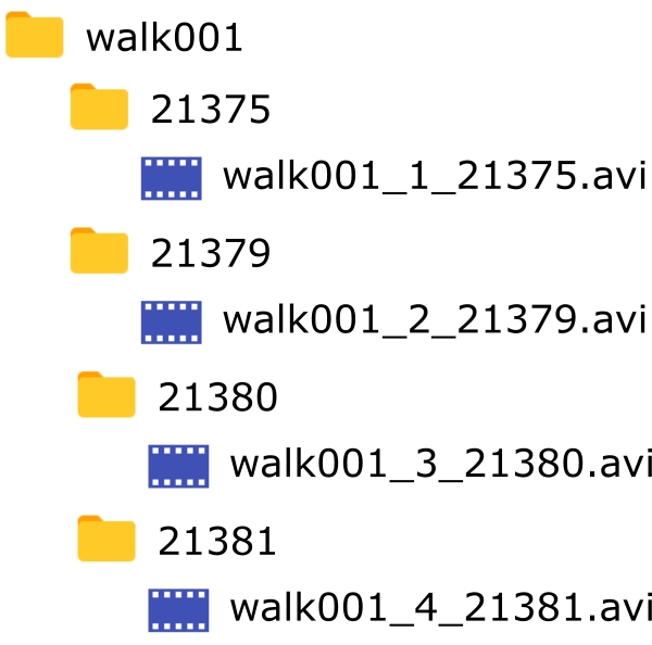
There are a variety of tools available within Theia3D Batch to organize and analyze multiple trials. The data to be processed must be in a single directory that can contain as many levels of subdirectories as desired to organize the data. However, each branch of the directory must end with a folder containing the data for a single trial. This must be a folder of video data as described in that also contains the calibration file for the trial. It is critical that the IDs of the cameras in the calibration file are the same as the IDs of the video file subfolders. When using this tool, the first step is to make sure your video data are organized and the calibration has been added to the files. Once these steps are complete, your data is prepared for batch processing. Proceed to Settings and for details on setting up and executing a batch analysis.
If the global coordinate system is in different positions and/or orientations in each of the camera views, this indicates that an incorrect calibration file was loaded. If the loaded calibration file has camera IDs that match those for the loaded videos but the calibration corresponds to a different camera setup, the calibration file can still be loaded successfully. However, this will lead to the camera system being incorrectly calibrated and the global coordinate system will not appear in the location or orientation that is expected for the loaded video data. If this issue goes unnoticed and the trial is then processed, it will lead to the Track People Incomplete error dialog.
Calibration is a crucial step for any 3D motion capture solution, and is equally important for Theia3D markerless motion capture data. The recommended calibration method depends on your camera system, but the concept and result is the same across all: determine the intrinsic and extrinsic parameters for all cameras in your system. These parameters allow lens effects and the 3D position and orientation of each camera to be determined, which is the key to producing robust 3D reconstructions. See Data Collection for details on recording intrinsic and extrinsic calibrations, and Calibration Menu for details on processing calibration trials.
The calibration methods supported by Theia3D include:
Chessboard calibration, using a large printed chessboard pattern to automatically obtain intrinsic and extrinsic camera parameters.
Third-party calibrations, such as wand calibrations implemented by third-party motion capture hardware suppliers.
Object calibration, using an object with known dimensions or with precisely measured key point positions to manually obtain extrinsic camera parameters.
Once you have obtained sufficient calibration data, the next step is collecting your movement trials. Theia3D produces robust 3D pose estimates across varying environments, for humans wearing typical body-fitting clothing, and is task-agnostic. Therefore, if the human(s) in your video are clearly visible and captured with appropriate resolution, frame rate, and exposure, the Theia3D algorithms can generally track their motion without issue. Record your movement data with relative freedom and ease, following the recommendations outlined in the Data Collection Principles section.
Having collected calibration and movement trials, you have everything required to process your markerless motion capture data. Theia3D includes several tools to help organize your data as required, process and check your camera system calibration, and analyze your movement trials. If you have collected numerous movement trials, you can use the accompanying Theia3D Batch application to batch analyze your trials without active supervision on your part; however, we always recommend manually checking your calibrations and a few trials in Theia3D first. Detailed information on the Theia3D Batch companion application can be found in Batch Processing .
Cameras as close as possible to the capture volume, while ensuring the entire capture volume remains within view for all cameras.
Cameras 4-8 feet (1-2.5 m) above the ground.
Avoid partial views of subjects, such as lower body or upper body only.
Avoid unusual camera views, especially those positioned very high or very low, or extremely tilted.
Aim for a symmetrical camera setup that surrounds the entire capture volume, such as a circle, oval, or rectangle.
The camera settings you choose will depend on the movements being collected. Selection of appropriate camera settings is crucial for collecting clear, crisp video images. The most important camera settings to consider include:
Frame rate: fast movements require high frame rates, to capture the movement smoothly. Check out this blog post for discussion and recommendations.
Shutter speed / Exposure: should be set to ensure the subject and their body segments are not blurry during the movement. Faster shutter speeds or shorter exposures will capture images with less movement blur, but may reduce the image brightness.
If you are collecting high-speed movements, you may need to consider introducing additional light into your capture volume in order to capture videos that are adequately bright. In general, faster movements require higher frame rates, faster shutter speeds / shorter exposures, and more light.
Theia3D provides 3D pose estimates that are robust to changes in attire. General recommendations for subject attire include:
Body-fitting clothing. Each limb should be discernible from the rest of the body.
Clothing should provide rich visual features, such as visible creasing, shadows, or other textures.
Lighting is often more important than attire color, as it impacts the visual richness of the attire. Under adequate lighting conditions black attire is acceptable, but lighter colors generally provide more visual features, especially in low-light environments.
Slowly ‘show’ the chessboard to groupings of 3 or more cameras while varying the position and orientation of the chessboard slightly. Ensure the chessboard is visible to cameras that overlap between groupings, ideally so that no fewer than 3 cameras can see the chessboard at all times. Focus on achieving groupings of 3+ cameras at all times.
When you are confident that all cameras have had sufficient views of the chessboard, slowly place the chessboard on the ground, aligned with your preselected marks.
Ensure you are not obstructing the view of the chessboard in any cameras during this localization phase.
End the recording.
Record object calibrations trials at a relatively low frame rate (20-30 Hz) to reduce file size and processing time.
Object calibration trials only need to be a few seconds long.
Place your calibration object within the capture volume, at the desired position and orientation to define the global coordinate system.
Ensure the key points on your calibration object are visible in every camera view, and there are no obstructions.
Begin the recording.
After a few seconds, end the recording.
To process extrinsic object calibrations, see Object Calibration.
Theia3D requires six or more camera views in order to load any video data. If at least six cameras were used to collect the data, locate the missing videos and add them to the trial folder in properly formatted camera ID folders. If fewer than six cameras were used to collect the data, it cannot be loaded and should be recollected with six or more cameras.

Set the opacity of the skeletons, 3D segments, and local coordinate systems rendered in the 2D views. The slider ranges from 0 (transparent) to 100 (opaque).
If selected, the filtered pose of the skeletons will be rendered. If not selected, the unfiltered pose will be rendered. (Default: Off)

Reduce the Frame Grab Step If the chessboard was detected in too few overlapping frames between camera groupings to form a continuous volume, it may be possible to calibrate the system with a lower Frame Grab Step value. Lower the Frame Grab Step value and run the calibration again.
Collect a new calibration trial. If it is not possible to reduce the Frame Grab Step to increase the overlapping visibility of the chessboard, it will be required to record a new calibration trial. If the camera system has not been taken down or modified since the data were collected and the data were collected relatively recently, a new calibration trial can be recorded. When recording the new calibration trial(s), be sure to focus on achieving an overlap in visibility of the chessboard surface in 3 or more cameras throughout the trial, and ensure that all camera groupings are linked by this overlap.

Check that the calibration file is an extrinsic calibration file. The selected calibration file may be a lens intrinsic calibration file, rather than an extrinsic calibration file. Confirm that you selected the correct calibration file, which was either saved after processing a chessboard or object calibration in Theia3D, or was generated by third party software such as Qualisys Track Manager or Vicon Nexus following wand calibration.
Check that the calibration file has not been modified. The selected calibration file may have been modified, and some calibration parameters may have been deleted. If parts of the calibration file have been modified or deleted, you may need to replace it with a backup of the original calibration file (if generated from third party software), or generate a new calibration file by reprocessing the chessboard or object calibration trial in Theia3D.

Record a new calibration. If the camera system has not be taken down or modified since the data were collected and the data were collected relatively recently (within 48 hours), a new calibration trial can be recorded. A new calibration may resolve the calibration issue and tracking errors in the movement trial.
Use the Check Calibration tool. As indicated by the error dialog, it may be possible to resolve or improve the camera calibration using the Check Calibration tool. Apply this tool to obtain and potential improvements.

Replace any missing video files. If the workspace failed to load due to one or more missing video files and the raw video data for the trial is still available, identify which video files are missing from the workspace folder and copy them from the raw video data trial folder.
Reprocess the trial and replace the saved workspace. If the workspace failed to load due to one or more missing .t3d files, it is necessary to reprocess the trial from the raw data. Follow the typical steps for processing an individual movement trial: load videos, load calibration, load or change the preferences, run analysis, and save workspace.


This section describes the basic camera system requirements for recording data to be used with Theia3D. See Data Collection for additional recommendations and principles to follow when recording video data for Theia3D.
Theia3D requires a minimum of six cameras for tracking; however, we recommend a minimum of eight cameras for most capture volumes. The number of cameras required will increase with movement complexity, capture volume size, capture volume complexity, and the number of people to be tracked. The field of view and joint visibility requirements outlined below are the best guides when determining the number of cameras required for a specific capture volume.
The cameras must capture synchronous videos with identical start times and durations to be used with Theia3D.
Person identification and tracking perform best when the people of interest are fully visible and cover a large percentage of the fields of view of the cameras. In most applications a height of 500 pixels is adequate - this requirement may increase based on camera setup, focus, and image quality. It is important that the people of interest are in focus and clearly visible.
Ideal tracking conditions are achieved when all joints are visible in all cameras; however, this is rarely attainable due to occlusions from other limbs, people, and the environment. At a minimum, each joint must be visible in at least three cameras. When setting up the cameras it is important to position and orient the cameras in a way that minimizes occlusions while simultaneously providing views of the subject(s) from varying angles to improve joint depth and position calculations. For example, a purely sagittal view results in several occlusions and poor tracking from that view but provides useful information for identify the depth of joints tracked in a more frontal view.
Theia3D does not require people to wear specific clothing to be tracked. However, loose or baggy clothing may result in lower quality tracking. As a general rule, if you can easily identify joints in the camera images, then Theia3D can infer the joint positions as well.
Unstable camera connections are often (but not always) due to faulty POE splitters, especially if it seems to be the same camera(s) with issues. Try following the steps below to test if this is the case:
Open the Sony browser interface.
Connect the Master camera control box to the network switch, with all other cameras disconnected.
Make sure a panel appears for the Master camera in the browser, but don't turn it on yet.
Starting with one of the cameras you've had issues with, disconnect the ethernet cable from the POE splitter, and disconnect the POE splitter from the control box. We'll be leaving the POE splitter out of the setup for now.
Connect the ethernet cable directly between the network switch and the camera control box.
Using the USB charging cable and brick that were included with the control box, connect the control box directly to a power outlet.
Wait for the camera panel to appear in the browser interface, then select both cameras and turn them On. If the connection is stable, this is a good indicator that the POE splitter is the issue.
Repeat this test for all cameras that have had unstable connections previously.
If the calibration file is not visible when using the Load Calibration File button or the Assign Calibration Files tool and the calibration file is an .xcp file exported by Vicon Nexus, the file browser window may be filtering for .txt files only.
Use the dropdown file filter selector in the file browser window to allow .xcp files to be shown.
If Theia3D is failing to launch fully and is freezing after creating the main application window, this issue typically occurs after a change to the computer monitor setup.
To resolve this issue, open the Windows Registry Editor and navigate to the folder: Computer\HKEY_CURRENT_USER\Software\Theia. Right-click on the “Theia” folder, and choose delete. Close the Registry Editor, and restart the computer. After restarting, attempt to open Theia3D. This should allow the application to launch fully.
If Theia3D crashes when processing a calibration or movement trial, this issue is usually due to the GPU RAM becoming maxed out immediately when attempting to perform the processing. Typically, the root cause of this issue is too high of a GPU RAM requirement from the computer monitor setup, usually due to the use of multiple monitors or individual very high resolution monitors.
To reduce the GPU RAM requirements, try reducing the number or resolution of the monitors connected to the GPU.
Initialization issues come up occasionally. This process may need to be repeated if there is more than one camera that is having this issue.
Place all cameras on Standby.
Disconnect all cameras from the network switch.
Turn the control box for the problematic camera to OFF and MASTER.
Connect the problematic camera to the network switch.
Turn the control box to ON.
Connect to the browser GUI, and attempt to initialize. Give this some time, and try a few times if necessary.
If initialization is successful, put the camera on Standby from the browser GUI and close the browser once the camera is on Standby.
Turn the control box to OFF, then switch to CLIENT.
Now, connect the original MASTER camera to the network switch (check that it is OFF first).
Turn the problematic control box to ON.
Turn the master control box to ON.
With only these two cameras connected, launch the browser GUI and allow it some time to load. Do not initialize.
If the cameras connect successfully, slowly add the other cameras to the system one by one, allowing time for each camera to appear and the system to stabilize before adding the next camera.
Pose files can also be saved as .fbx file formats for use in animation and other software tools that utilize this file format. Use the Save Skeleton Poses button to save skeleton pose .fbx files, or navigate to Save Skeleton Poses under the File Menu.
FBX file outputs can be saved with a variety of different segment coordinate system conventions for your convenience.
Toggle the boxes around all people found in each 2D view. The color of the box around each identified person is unique to that person and the same in all views. The boxes around people who have not been identified are grey. Person identifications are also printed in the upper left corner of the boxes.
3D segments can be toggled on and off using the sidebar button.
Toggle the 3D segments of each identified person in the 2D views and in the 3D view. The color of the segments is unique to the identifed person and matches the color of the 2D boxes corresponding to that person.
Skeletons can be toggled on and off using the sidebar button.
Toggle the skeletons of each identified person in the 2D views and in the 3D view. The color of each skeleton is unique to the identified person and matches the color of the 2D boxes corresponding to that person.
Local segment coordinate systems can be toggled on and off using the sidebar button.
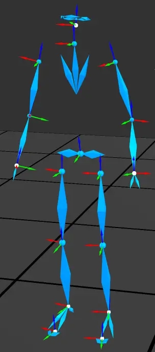
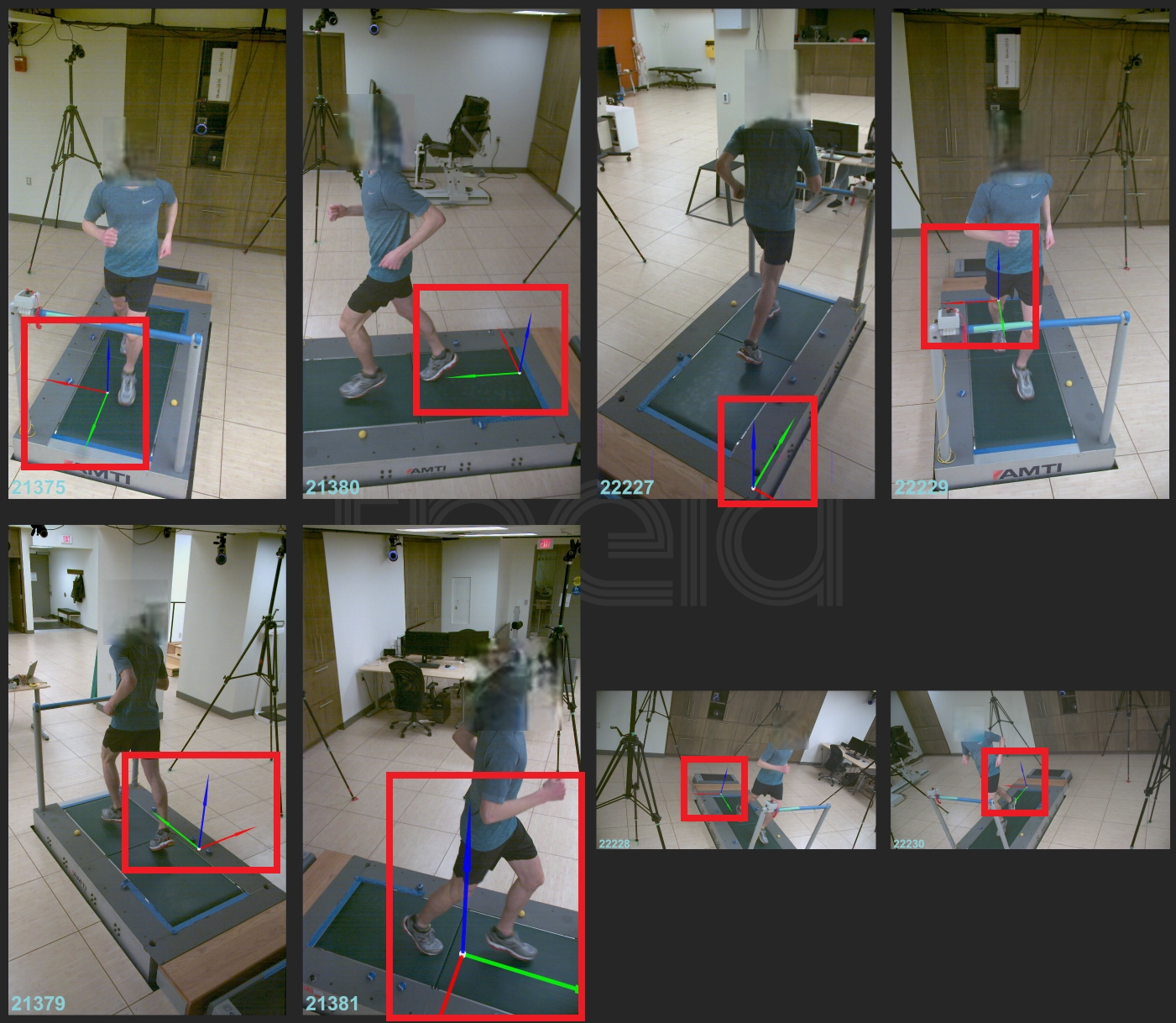
Toggle the local coordinate systems of segments and cameras in the 2D views and in the 3D view. Note that the local coordinate systems of the segments are only shown if the segments or skeleton are visible. The origin of each coordinate system is a white sphere, the x-axis is a red arrow, the y-axis is a green arrow, and the z-axis is a blue arrow.


Path to the video file for the currently selected camera.
Name of the lowest folder level.
Video image resolution, in pixels.
Video file length, in frames.
Video file frame rate, in frames per second.
Number of frames offset between the current video file and other synchronized video files from the current recording. Generally a value of 0 is expected for most camera systems that record frame synchronized videos using on a start/stop trigger signal. Sony RX0 II camera systems may have non-zero values here, as these systems use timecode video synchronization for post-hoc alignment of videos between cameras.
Confirm the correct calibration was loaded. Double check that you loaded the correct calibration file for the camera setup used to record the loaded video data. This calibration file should have been saved after processing the calibration trial recorded during the same collection session as the loaded movement data.
Note that administrator privileges are required for installation and licensing.
The Video Enhancement tool allows you to improve video quality before processing data, which can be especially useful for calibration under challenging lighting conditions. Changes made using this tool are previewed for the loaded 2D views, and any enhancements are applied before running the 2D inference, lens calibration, or chessboard calibration processes. Therefore, what you see in the 2D views is how the video data will be processed.
Apply the selected enhancements to all camera views. Alternatively, select an individual camera from the dropdown menu to apply individual camera enhancements.
Increase or decrease the brightness of the videos. Default (no enhancement) is 0.
Increase the contrast of the videos. Default (no enhancement) is 1.00.
Adjust the white balance of the videos by performing a color correction using a baseline white color. Enable White Balance by selecting the square, and click on the white rectangle to open the color picker. You can select a specific color, input color values, or use the Pick Screen Color option to select a pixel from within your loaded videos of a white surface such as the chessboard.
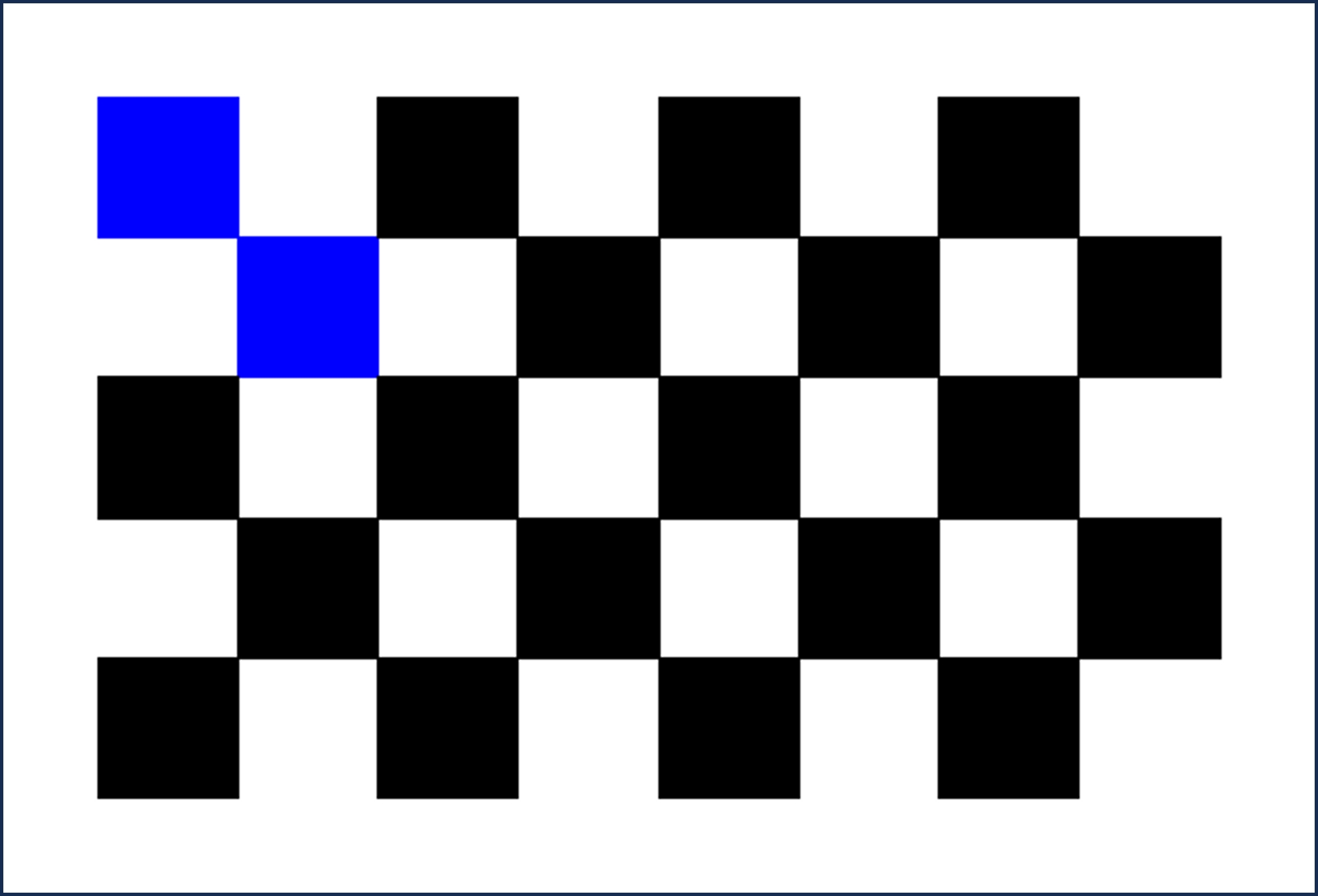
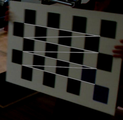
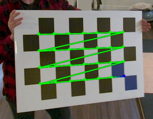
Shows which pixels are detected as blue by the chessboard calibration algorithm. This is useful for adjusting your videos before processing a chessboard calibration to ensure the blue squares are detected. The global coordinate system origin is defined at the intersection of the blue squares, which must be detected in order to define the origin.
Reset all changes to default values, removing any video enhancements.
The Setup preferences pane contains options and parameters for the software setup and startup.
Path to Visual3D.exe location. Must be set in order to load data in Visual3D from Theia3D. Use the Visual3D Path button to browse to and select your Visual3D.exe file.
Show or hide the startup/GPU selection dialog when Theia3D launches.
Shortcut: Ctrl + ,
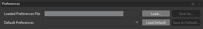
The settings available at the top of the preferences pane enable the user to load, save, and save default preferences.
Displays the path to the preferences file from which the current preferences were loaded.
Load: Allows the selection of a new preferences .pxt file.
Save As: Allows the current preferences to be saved as a new .pxt file.
Load: Allows previously specified default preferences to be selected and loaded.
Save As Default: Allows the current preferences to be saved as a new set of default preferences.
The startup window appears if ‘Select GPUs on launch’ is enabled in the Theia3D setup preferences.
Select which graphics card(s) to use when running Theia3D.
Select which person detector to use when running Theia3D, and set the skip frames count.
Small: fastest, may be slightly less accurate than Default or Large.
Default: recommended.
Large: slowest, may be slightly more accurate than Default or Small (currently disabled).
Skip frames sets the frame interval used during the analysis process to identify and track people. Default is 1, Maximum is 5. Increasing the Skip Frames value will speed up the analysis. The Skip frames value should not be used for fast movements recorded at relatively low frame rates, or movements with multiple closely-interacting individuals, as the person identification may be affected.
Select which joint detector to use when running Theia3D.
Small: fastest, may be slightly less accurate than Large (currently disabled).
Large: (default) slowest, may be slightly more accurate than Small.
Add Hands: (available as a license add-on by special request) Include hand model, which improves hand tracking through localization. Requires camera views that are positioned specifically to capture the hands and upper body. Please reach out to [email protected] for more information.
Available as a license add-on by special request.
Listen Mode allows a directory to be selected where data is saved during data collection. The selected directory will be actively monitored for new, unprocessed data which will be automatically analyzed as it is detected. This allows data to be processed during an active data collection session, enabling all processing to be completed by the end of the collection session.
The camera calibration file contains the calibrations for all of the cameras using a structure similar to XML. An example calibration file is provided with the sample data. Key elements and attributes of the calibration file are outlined here. Note that Qualisys calibrations exported from QTM as .txt files and Vicon calibrations (.xcp) can also be used.
Top level element with no attributes.
Grouping element that holds <camera> child elements. It has no attributes.
Element that holds the calibration results metrics, as described in .
Element that holds the calibration information for a single camera. Required attributes are: active, serial, and viewrotation. Required child elements are: <transform> and <intrinsic>.
active: 1 if the camera is used, 0 if unused.
serial: The camera ID. Must be unique to the camera and match the camera ID used to name the video subfolders.
viewrotation: Rotation of the camera. 0 if upright, 180 if upside down, 90 or 270 if sideways. This is calculated from the rotation matrix of the calibration.
Translation and rotation components of the transformation from global to camera coordinates (p→cam=Rp→global+t→). Required attributes are x, y, z and r11 through r33.
x, y, z: Elements of the translation component (t→) of the transformation. Expressed in mm.
rij: Elements of row i and column j of the rotation component (R) of the transformation.
Intrinsic camera parameters. Required attributes are: focallength, sensorMinU, sensorMaxU, sensorMinV, sensorMaxV, focalLengthU, focalLengthV, centerPointU, centerPointV, skew, radialDistortion1-3, and tengentialDistortion1-2.
focallength: Focal length of the lens in mm.
sensorMinU: Minimum u coordinate of the sensor in pixels.
sensorMaxU: Maximum u coordinate of the sensor in pixels.
sensorMinV: Minimum v coordinate of the sensor in pixels.
Cancel the currently running analysis. This option is available (and replaces all other options) only when analysis is running.
Detect people in each of the loaded videos. When complete, boxes are drawn around the detected people in the video overlays if Show Boxes is selected in the Display menu. Video data and calibration must be loaded before running Run 2D.
Identify people across views (i.e., determine “who is who” in each of the views). Identification requires the person to be clearly visible in at least three views simultaneously. Each identified person is assigned a unique color that is applied to their boxes, segments, and skeleton. Run 2D must be completed before running Track People.
Solve the 3D pose of each identified person. The kinematic model is scaled and the pose of the model is solved using inverse kinematics. A description of the model can be found in . Refer to for information about using a previously saved model to perform the inverse kinematics step. Track People must be complete before running Solve Skeleton.
Runs: Track People and Solve Skeleton. Run 2D must be completed.
Shortcut: Ctrl + F
Runs: Run 2D, Track People, and Solve Skeleton. Video data and calibration must be loaded.
The Modify People IDs tool allows you to swap the unique person ID numbers assigned to each person when multiple people are tracked in a trial. Click and drag an ID and drop it onto another ID to swap those two ID numbers. This change to the IDs is immediately visible in the 2D and 3D views. You can also right-click on an ID to display a context menu with options for removing that tracked person or making it person 0.
Note: removing a person cannot be undone (except by re-running Track People).
This error message arises when loading video data. It indicates that the folder selected when browsing to load video data contains data that is not formatted as required by Theia3D (See Data Formats). The video data may all be located within a single folder (i.e. all video files together in one folder), instead of each video file being nested within its own folder with a matching camera ID folder name.
, then try again. In order to load the desired video data, it must first be organized as required by Theia3D. This can be done using the Organize Videos tool under the Tools dropdown menu. For detailed instructions on the use of this tool, you can watch the Organize Tools tutorial video.
first. As indicated in the error message, data that is all located within one folder instead of within camera ID folders can be loaded if the calibration file for the movement trial is loaded before the video data. Using this approach, the video data will then be automatically organized within camera ID folders to meet the Theia3D data organization requirements moving forward.
There are a few reasons why the skeleton may appear to be jittery when reviewing a processed movement trial:
The Smoothing Frequency is too high. If the movement is somewhat slow and the Smoothing Frequency is set to a relatively high value, the filter will not be effect in reducing noise in the pose estimations, resulting in noise or jitter in the skeleton.
The person or body segment is not sufficiently visible. If the person or their body segments are marginally visible, the pose estimates may be unstable resulting in noise or jitter in the skeleton. This can be a result of low resolution, low light, high levels of noise in the video images, and/or challenging clothing/background combinations.
Some possible solutions for the above causes of a jittery skeleton include:
Reduce the Smoothing Frequency. If the skeleton jitter is due to a relatively high Smoothing Frequency being used for a slow movement, the jitter may be reduced by using a lower Smoothing Frequency. After adjusting the Smoothing Frequency in the , you only need to run the analysis step to view the updated pose results.
Use the tool to improve the video quality. If the videos are too dark or not properly white-balanced, they may be improved using the Enhance Videos tool. This can improve the visibility of body segments and improve tracking quality. After adjusting these settings, you will need to use the button to perform all analysis steps.
Adjust the camera system setup to improve participant visibility. If the person is not sufficiently visible to be tracked in the videos, the camera system setup and settings will need to be adjusted to improve the visibility of the person. You may need to move the participant within the capture volume, move or reorient your cameras, or adjust your camera settings to improve the visibility of the participant.
This error message arises when attempting to use the Organize Videos Tool to organize video files as required by Theia3D. Theia3D requires video data to be .mp4 or .avi file formats, so if the directory selected for organizing contains video files of a different format (e.g. .mkv, .mov, etc.) Theia3D will be unable to organize or load these videos.
To ensure your video data can be organized, loaded, and processed by Theia3D, they should be in .mp4 or .avi file formats. If possible, re-export the original videos to the correct file format, or convert the existing video files
If the coordinate system is out of place in one camera view, but is positioned and oriented as expected in the remainder of the views, it is likely that the position of the single camera changed between the recording of the calibration trial and the loaded movement trial. The camera view may have been intentionally changed, as in the case of adjusting a camera view to better capture the volume, or it may have been accidentally changed, in the case of a tripod being bumped by a passerby.
Use a different calibration from the same session. If multiple calibration trials were recorded during the data collection, try loading one of the other calibration files. If any of the other calibrations were recorded after the camera was moved, they should be able to properly calibrate the camera system. This is the best possible solution, and follows our recommendation to record at least two calibration trials per data collection (one at the start, one at the end).
If possible, collect a new calibration trial. If the cameras have not been moved since the movement trial was recorded, the next best solution is to record a new calibration trial with the cameras in their current position and orientation. This calibration trial can then be processed and assigned to the movement trial, allowing the camera system to be calibrated properly.
Exclude the moved camera view. If it is no longer possible to record an additional calibration trial (i.e. the camera system has been taken down), the camera that was moved can be excluded from the analysis using the
This error message arises when loading video data. It indicates that the videos from the selected trial are of unequal lengths.
Theia3D requires videos to be of equal lengths in order to be loaded. If your videos are of different lengths, this usually indicates an issue with your camera hardware setup or settings, or video download settings.For OptiTrack Prime Color cameras, verify that you have selected the correct video export settings, particularly Dropped Frames: Black Frame. If Dropped Frames: Drop Frame was used, this can result in exported video files being unequal in length, and the videos should be exported again using the correct setting.
This error message arises when loading video data. It indicates that the videos files from the selected trial were written using an unsupported video chroma format for codec h264. Supported formats are 8, 10, or 12 bit YUV 4:2:0.
Theia3D requires video files to be encoded using certain supported video codecs and color chroma formats. If the videos you are trying to load were created with an unsupported video chroma format, they cannot be loaded by Theia3D. When this error is encountered, the best solution is to re-export or convert the videos to a supported chroma format.
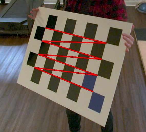
This error message arises when the chessboard calibration algorithm is unable to calculate the position and orientation of the cameras relative to the chessboard. More than one chessboard may have been detected in the calibration trial videos, which can be caused by extra chessboards present in the capture volume or mirrors positioned around the capture volume.
Reduce the Frame Grab Step. If the chessboard was detected in too few frames to be calibrated due to a high Frame Grab Step value being used, it may be possible to calibrate the system with a lower Frame Grab Step value. Lower the Frame Grab Step value and run the calibration again.
Collect a new calibration trial. If the camera system has not be taken down or modified since the data were collected and the data were collected relatively recently (within 48 hours), a new calibration trial can be recorded. Address the source of the problem (e.g. remove extra chessboards or cover mirrors) and collect a new calibration trial.
There are a few reasons why the skeleton may be completely missing when reviewing a processed movement trial:
The display option is deselected. If the Show Skeleton option is not selected, the 3D skeleton reconstruction will not be displayed on the 2D videos.
The is set too low for the movement. If the Smoothing Frequency is set too low, it is possible for the moving body to be detected as an outlier and excluded from the tracking. This typically occurs when the movement is very fast and the Smoothing Frequency is set relatively low.
The person is not tracked. If the Max People setting in the is set to an integer value (i.e. not No Max) and there are other people who are more visible in the videos, the main person of interest may not be tracked and they will not have a skeleton.
The person is not sufficiently visible to be tracked. If the person is not sufficiently visible in 3 or more cameras due to the camera positioning, orientation, or the quality of the video images, they may not be tracked.
Some possible solutions corresponding to the above causes for a completely missing skeleton are as follows:
Select Show Skeleton display option. Select the display option in the dropdown menu.
Increase the Smoothing Frequency. If the cause of the missing skeleton is a low Smoothing Frequency resulting in the entire body being detected as an outlier, try increasing the Smoothing Frequency to allow the movement to be tracked. After adjusting the Smoothing Frequency in the , you only need to run the analysis step to view the updated pose results.
Set the Max People setting to No Max. If the person of interest was not tracked but other people within the videos were, set the Max People setting to No Max to ensure the person of interest is also tracked. After modifying this setting, you only need to run the analysis option to view the updated results.
Synchronization of the video images can be checked after the trial has been analyzed fully. For each view, the 2D representation of the skeleton in that view is compared to the 3D skeleton computed from all views. If the alignment for a given view can be improved by shifting its video sequence forward or backward in time, this frame offset is reported in the dialog. You can then choose to correct the synchronization by applying these offsets to the out-of-sync views and clearing the entire analysis.
The following video provides step-by-step instructions for setting up and using your cameras to collect data for use with Theia3D. This includes changing camera settings, synchronizing the cameras, recording data, and downloading videos from the cameras through the web interface. This tutorial demonstrates the basic functionality and recommended settings of the Sony camera control interface. Refer to the Sony documentation for information about other settings and more advanced functionality.
NOTE: This video recommends setting the Shoot Mode to (Movie) Program Auto, however we no longer recommend this option. To achieve crisp images without movement blur, we recommend setting the Shoot Mode to (Movie) Manual Exposure, which allows you to select a specific Shutter Speed. Using a shorter Shutter Speed such as 1/500 or 1/1000 will provide crisper images with limited movement blur, but may result in dark images. If your videos appear dark, adjust the ISO setting to increase the brightness of the image. If you are using ISO AUTO, you may need to increase the maximum ISO threshold to allow a sufficiently high ISO to be used.
Using the digital zoom is not recommended, as the default Sony RX0 II intrinsic parameters built into Theia3D will no longer apply, and you will be required to obtain new intrinsic parameters for your cameras.
The preferences file associated with each trial determines the prefences used when that trial is analyzed. This allows you to customize the preferences used across different trials within a single batch analysis, providing greater control over the analysis process. If there are not any preferences .pxt files assigned to the trials within your selected batch analysis root folder, the Preferences column will indicate that the default preferences will be used for your trials.
Right-clicking on the preferences column displays a context menu for the preferences, with the following options:
Opens the Settings dialog to change the preferences for the current trial.
Copies the preferences of the current trial to the clipboard.
Pastes the preferences in the clipboard to the selected trials, or if no trials are selected, to the current trial.
An example procedure for modifying the preferences assigned to a subset of trials is as follows:
Select one of the trials in the subset whose preferences you wish to modify.
Right-click on the Preferences column for that trial, and select Edit.
Modify the preferences in the Settings window to your desired preferences, and click Save.
Right-click on the Preferences column for the same trial, and select Copy.
The most common reason for the projected 3D skeleton (or 3D body segments) to be consistently outside the body in the 2D videos is that there is an issue with the calibration file. The calibration of the camera system determines how the calculated 3D pose, represented by the 3D skeleton or 3D segments, is projected onto the 2D videos. Therefore, if there is an issue with the calibration file the 3D skeleton can be projected incorrectly onto the 2D videos, resulting in the skeleton or body segments appearing outside of the body.
To confirm that the calibration file is the issue, take note of whether the global coordinate system is positioned and oriented as expected in the camera view(s) for which the projected skeleton is outside the body. If the global coordinate system is not positioned correctly in one or more camera views, this confirms the issue is with the calibration file. Having confirmed the calibration file is the issue, please review the appropriate troubleshooting section for coordinate system issues.
This error message arises when loading video data. It indicates that the videos files from the selected trial were written using an unsupported video file codec.
Theia3D requires video files to be encoded using certain supported video codecs. If the videos you are trying to load were encoded with an unsupported codec, they cannot be loaded by Theia3D. When this error is encountered, the best solution is to re-export the videos in a supported codec, or to convert the existing videos to a supported codec.
For OptiTrack Prime Color cameras, verify that you have selected the correct video export settings, particularly Video Format: MJPEG. If the incorrect video format was selected, the video files may not be written using a video codec supported by Theia3D and will need to exported from Motive again, in the proper format.
Intrinsic lens calibration trials are used to determine parameters associated with the camera lenses and are used to correct for distortion and other visual effects. Lens calibration trials are required for all camera systems that make use of a chessboard calibration method, except for Sony RX0-ii cameras. Users with wand calibration-capable systems (e.g. Qualisys Miqus, Vicon Vue or FLIR Blackfly S systems) are not required to complete lens calibration unless they are planning to use the chessboard calibration method.
Lens calibrations must be performed at least once per video resolution that will be used to record movement data, and any time the lenses or focal lengths change. If you intend on collecting data at 1080p, 720p, and 540p, you will need to record separate lens calibration trials at each of those resolutions.
The Settings section provides widgets to set up the current batch analysis. The Browse button enables the user to select the root folder. The data to be processed must be organized in this single root folder that can contain as many levels of subdirectories as desired to organize the data. However, each branch of the directory must end with a folder containing the data for a single trial. This must be a folder of video data as described in that also contains the calibration files for the cameras. It is critical that the IDs of the cameras in the calibration file are the same as the IDs of the video file subfolders. The Settings section enables the user to input the batch analysis root directory and the output format that will be generated by the batch analysis:
If the global coordinate system is in an incorrect but consistent position and/or orientation in all camera views, this typically indicates that a different frame was used to set the origin than what was selected in the . This is often caused by the chessboard or its blue squares not being sufficiently visible in the selected Origin Frame, which can be a result of the chessboard being too far from the cameras, challenging lighting conditions, or the cameras being parallel with the surface of the chessboard. In this case, Theia3D searches for the nearest frame in which the chessboard is adequately detected for localization, and uses that frame instead, which can lead to a floating global coordinate system in an undesirable position and orientation.
After installing Theia software, it is necessary to activate the license prior to using the software. To activate your Theia3D license, run Theia3D as an administrator by right-clicking on the icon and choosing 'Run as administrator'.
When running Theia3D as an administrator, a prompt to enter the license key will appear, as below. Enter your license key in this window and click Activate. You can access your license key from the using the login information provided at the time of purchase.
If the PC is connected to the internet, the license will automatically activate and Theia3D will open.
The Adjust Calibration tool can be used to modify the position and orientation of the global coordinate system (GCS) after completing a chessboard or object calibration, or after loading an existing calibration file. The GCS projection on each 2D camera view and within the 3D View is updated live as the Position and Angle sliders are used to modify these parameters of the GCS localization.
This tool can be used to reposition the GCS to a more desirable position or orientation if the desired origin frame could not be used from the chessboard calibration trial, for any other methodological reason that requires the GCS in a specific position.
X, Y, Z sliders can be used to change the position of the GCS relative to its original position, measured in mm.
In general, the 3D skeleton appears to be incomplete when one independent part of the kinematic chain cannot be tracked. The body parts that are able to disappear will depend on the joint constraints you have selected in the Analysis section of the , and the cause of their disappearance can vary.
For example, when Enable Free Arms is not selected, the shoulder joint is modelled with 3 degrees of freedom (DOF), allowing full rotational freedom but no translation of the upper arm relative to the torso. Therefore, if one of the arms cannot be tracked, then the entire left arm + torso + right arm chain will disappear. However, if Enable Free Arms is selected the shoulder joint is modelled with 6 DOF, allowing the arms to be tracked independently of the torso. This allows any of the left arm/torso/right arm segments to be tracked, even if one of the other segments cannot be tracked.
There are several reasons why a body segment may disappear in a processed movement trial:
There are currently three available models in Theia3D:
Consists of two kinematic chains: lower body (pelvis and legs) and upper body (torso, arms, and head).
No abdomen or neck segments.
This error arises when Theia3D is not able to adequately track the people identified within the 2D views throughout 3D space. There are two primary causes of this error:
An incorrect calibration file was loaded. If an incorrect calibration file was loaded, meaning that the camera system is not properly calibrated, then it will not be possible for the people identified within the 2D videos to be tracked throughout 3D space.
The Toggle Views tool can be used to turn on and off individual camera views for the currently loaded trial. When turned off, camera views are greyed out in the 2D viewer area, and are not used when analyzing the trial.
Toggle Views adjustments are included when saving preferences files.
Select the remaining trials in the subset whose preferences you wish to modify, using shift+click to select sequential groups of trials or ctrl+click to select individual trials.
Right-click on the Preferences column for one of the currently selected trials, and select Paste.
Adjust the camera system setup or move the person to a more visible location within the volume. If the person is not sufficiently visible to be tracked in the videos, the camera system setup and settings will need to be adjusted to improve the visibility of the person. You may need to move the participant within the capture volume, move or reorient your cameras, or adjust your camera settings to improve the visibility of the participant.
The Smoothing Frequency is set too low. If the Smoothing Frequency is set too low, it is possible for the moving body part(s) to be detected as an outlier and excluded from the tracking. This typically occurs when the movement is very fast and the GCVSPL Cutoff Frequency is set relatively low.
The body segment is not sufficiently visible to be tracked reliably. If the body segment is occluded or otherwise difficult to discern in the videos due to poor lighting, dark clothing, a challenging pose, or other factors, it may not be possible to track the segment reliably and it will disappear.
Some possible solutions for incomplete skeleton tracking are as follows:
Increase the Smoothing Frequency. If the cause of the incomplete skeleton is a low Smoothing Frequency resulting in the body segment being detected as an outlier, try increasing the Smoothing Frequency to allow the movement to be tracked. After adjusting the Smoothing Frequency in the Preferences window, you only need to run the Solve Skeleton analysis step to view the updated pose results.
Use the Enhance Videos tool to improve the video quality. If the videos are too dark or not properly white-balanced, they may be improved using the Enhance Videos tool. This can improve the visibility of body segments and improve tracking quality. After adjusting these settings, you will need to use the Run Analysis button to perform all analysis steps.
Improve the quality of the data recorded by your camera system. If the data quality is insufficient to be able to clearly see all body segments, try improving the quality of the data collected by your camera system. You may need to make adjustments such as increasing the amount of ambient light, increasing the camera resolution, selecting appropriate frame rate and exposure settings, or moving the cameras closer to the participant to capture them with higher resolution.
X, Y, Z sliders can be used to change the orientation of the GCS relative to its original orientation, about the respective axis of the GCS, in degrees.
Reset the position and angle sliders to 0.0.
Apply the selected position and angle adjustments to the current camera system calibration.
Apply the selected position and angle adjustments to the current camera system calibration, and save the result as a new calibration .txt file.

The Analysis Bounding Box was used with dimensions (length, width, height) of 0. If the Restrict skeletons to bounding box option was selected but no dimensions were provided for the bounding box, the people visible in the 2D camera views cannot be tracked in 3D space and the Track people not complete error message will appear.
Check the Restrict skeletons to bounding box option. If you intended to use the Restrict skeletons to bounding box option, either provide the dimensions of your desired bounding box or use the Use Camera Locations option to define the bounding box. If you did not intend to use the Restrict skeletons to bounding box option, deselect it. After making either modification, you will need to Run Analysis (without 2D) to update the person tracking and modelling results.
Check that the correct calibration was loaded. If an incorrect calibration file was loaded, the camera system may not be calibrated properly leading to improper 3D reconstructions from the 2D data. Review the position and orientation of the global coordinate system in each 2D camera view - they should all show the global coordinate system at the same position and orientation. If the global coordinate system is out of place, it is likely that an incorrect calibration was loaded. Locate and load the correct calibration file, and Run Analysis again.
Check that there are people sufficiently visible to be tracked. If there are no people or insufficient views of any people captured in the videos, nobody will be tracked. Be sure that your cameras are set up to sufficiently capture any participants with 3 or more cameras at all times, and record new movement trials.


Note: If none are available for your GPU, they will be built automatically the first time Theia3D is run.
Copy your license key for safekeeping offline.
If you downloaded a Graphics Card Engine from the Theia Software Downloads portal, run the executable once the Theia3D application installer has finished.
sensorMaxV: Maximum v coordinate of the sensor in pixels.
focalLengthU: Focal length along the u axis in pixels.
focalLengthV: Focal length along the v axis in pixels.
centerPointU: Principal point u coordinate in pixels.
centerPointV: Principal point v coordinate in pixels.
skew: Skew coefficient. Non-zero if the image axes are not perpendicular. Note that non-zero skew is currently unsupported.
radialDistortion1-3: Radial distortion coefficients.
tangentialDistortion1-2: Tangential distortion coefficients.
Adjusting the aperture and focus of OptiTrack Prime Color cameras using the dials on their lenses does not necessitate new lens calibrations.
Record lens calibration trials at a relatively low frame rate (20-30 Hz) to reduce file size and processing time.
Keep the chessboard as flat as possible during the calibration trial.
Use a computer monitor facing the person performing the calibration to provide visual feedback during the calibration.
Move slowly and deliberately to prevent chessboard blur.
Lens calibrations can be performed for smaller groups or individual cameras and merged afterwards. If you are finding it challenging to calibrate all at once, try recording separate groups.
Place all cameras side by side on a desk or table, facing the same direction and capturing as similar views as possible. It is generally easier to calibrate the lenses with the cameras in 'landscape' orientation.
Stand at a distance where the chessboard occupies approximately 1/4 of the camera views.
Begin the recording.
Slowly move the chessboard in a systematic grid pattern, covering the entire field of view for every camera. Ensure the chessboard goes slightly beyond every edge of every camera field of view, and every corner.
Take a step back, and repeat Step 4., covering the camera fields of view again.
While covering the field of view, angle the chessboard slightly in multiple directions, varying its orientation throughout.
When you are confident that the entire field of view has been covered for all cameras, end the recording.
To process intrinsic lens calibrations, see Lens Calibration.
Currently selected batch analysis root folder.
Select the batch analysis root folder.
Refresh the batch analysis root folder to update the Trials list with changes to the folder.
If selected, a Theia3D workspace is saved for each trial in a folder called inputdirectory_workspace. This folder is in the same location and has the same structure as inputdirectory.
If selected, the pose data for all individuals tracked in each trial will be saved in a folder called inputdirectory_json. This folder is in the same location and has the same structure as intputdirectory.
If selected, the pose .c3d files will be saved for each trial in a folder called inputdirectory_c3d. This folder is in the same location and has the same structure as inputdirectory.
If selected, the pose .fbx files will be saved for each trial in a folder called inputdirectory_fbx. This folder is in the same location and has the same structure as inputdirectory. The coordinate system convention used in the .fbx file can be selected from the dropdown box.
(Only applicable when Save C3D is selected) If selected, the pose .c3d files will be created with file names that combine the folder names from the lowest n levels of the batch analysis folder hierarchy, where n is the selected Level dropdown value. For example, if selected and Level=3 for data that is structured as [subject] / [action] / [trial] / [camID], the output files will be named: [subject]_[action]_[trial]_pose_filt_#.c3d.
The About dialog shows the following information:
Software version number
Release date
Contact information

Use the Enhance Videos tool to improve chessboard visibility. One approach is the use the Enhance Videos tool to adjust the brightness, contrast, and white balance of the videos in an effort to improve the visibility of the chessboard in the desired origin frame. Use the Blue Mask tool to check if the blue squares are visible in the desired origin frame, and adjust the enhancement settings to improve their visibility. After enhancing the videos, reprocess the calibration trial.
Use the Adjust Origin option within the Object Calibration tool to manually annotate the chessboard in the desired origin position to set the global coordinate system. To use this approach, open the Object Calibration tool and use Load Object to load a .csv file containing 3D points for the chessboard pattern, or use the Add button to add these points directly. When using a standard Theia Markerless chessboard with 100 millimeter squares, the 3D points that describe the inner corners of the outside corner squares are: (0,0,0), (0,600,0), (300,600,0), and (300,0,0). With the chessboard object points loaded or created, double click on a view where these points are the most visible. While holding control, manually select these positions (i.e. the inner corners of the outer chessboard squares) in this view by carefully clicking on their location. When complete, repeat this process for a total of three or more camera views, then click Adjust Origin. This will maintain the relative positions and orientations of the cameras from the automatic calibration, but will move the reference frame to the correct location.
Use the tool to manually move and re-orient the global coordinate system. The Adjust Calibration tool under the Calibration dropdown menu can be used to modify the position and orientation of the global reference frame, relative to its original position. Use the x, y, and z sliders under the Position and Angle sections to translate and rotate the global coordinate system about those axes of the original global coordinate system. After modifying the global coordinate system as desired, choose Apply or Apply and Save to save the adjusted calibration as a new .txt file.
Use a different origin frame and adjust the chessboard calibration settings (Normal Axis, Long Axis). Another option to produce a more useful origin is to select a different origin frame and use the Normal Axis and Long Axis values in the dialog to modify the orientation of the global coordinate system relative to the chessboard during the new origin frame selection. For example, selecting a video frame in which the chessboard is positioned vertically standing on its long edge, setting Normal Axis to X, and Long Axis to Y would produce a vertical upwards Z axis and may produce a more useful origin.
After contacting Theia Support, enter the Activation Code as provided by our team and click Activate. The license activation will then be completed, and Theia3D will open.
If a manual license activation is required, please remember to include the License, System, and Token information provided in the warning dialog when contacting [email protected].


Flip X/Y/Z: Flip the X, Y, or Z angle plots.
The batch progress dialog displays the progress of the currently running batch analysis. Each trial in the batch is shown and can be expanded to show the separate analysis steps. State icons (circles) are shown, and correspond to the same states as described in Trials.
The view command results window shows the commands that have completed by Theia3D while handling and processing data, including specific inputs and outputs in the dropdown menus when expanded. The text color indicates the step status, where green indicates success and yellow indicates a warning is present.
Show all will show hidden, non-critical commands in the list.
Clear Results will clear any commands currently in the Commands list.
Shoulder joints and head segment are allowed 6 degrees of freedom.
Consists of one, whole-body kinematic chain.
Abdomen and neck segments included.
Shoulder joints are allowed 6 degrees of freedom.
Head is allowed 3 degrees of freedom.
Consists of five kinematic chains: lower body (pelvis and legs), torso, left arm, right arm, and head.
No abdomen or neck segments.
Shoulder joints and head segment are allowed 6 degrees of freedom.
Model pose can be exported to .c3d, .fbx, and .json files.
The .c3d files contain the 4x4 pose matrices for each model segment and the local coordinates of the anatomical landmarks of the distal segments of the model (feet, hands, head). These files can be processed using Visual3D.
The .fbx files contain the hierarchical skeleton, pose, and bone meshes of the animation model. The first frame of the file contains the model in a “T-Pose”. The skeleton must be solved using the Full Body Model in order to save pose files in FBX format.
The .json files contain information about how the trial was processed (Theia3D version, model, preferences, etc.) and the 4x4 pose matrices for each body segment for every frame of the trial.


The videos from each camera view are shown here and the 3D scene is projected onto each view. When all views cannot fit in the available area, arrows are shown and can be used to move through the available views. Double-click on a view to maximize it. When maximized, the mouse is used to zoom (scroll) and pan (right-click and drag) the view, and clicking on the arrows moves between views. Double-click the maximized view to restore it and show all views. Use Alt + right-click to inspect a view through a magnifying class - the level of magnification is controlled by the mouse wheel and reset with the ‘R’ key.
The 3D scene is rendered here. The mouse is used to rotate (left-click and drag), pan (right-click and drag), zoom (scroll), and inspect (Alt + right-click) the scene. The 3D scene contains the global coordinate system, cameras, and skeletons of each identified and tracked person. The origin of the global coordinate system is a white sphere, the x-axis is a red arrow, the y-axis is a green arrow, and the z-axis is a blue arrow. The scene enviroment, ground, and lighting can be modified from the menu accessed using the button at the top left of the 3D view.
The quick tools are shortcuts to the most common Theia3D commands. The entire processing pipeline can be executed using these shortcuts.
Most options can be toggled on and off using the quick tool display buttons.
The menu is divided into eight sections.
- Commands to load and save data.
- Commands to process data.
- Options to control what is displayed in the video overlays and 3D scene.
- Options to display joint angle results or monitor the progress of a batch analysis.
The video data can be played and paused using the play button on the left, or you can scroll through the trial using the timeline slider. The number to the right of the timeline indicates the current frame number, and the playback dropdown allows you to adjust the steps between frames that are displayed. When set to one, every frame is displayed, when set to two, every other frame is displayed, and so on.
Below the playback timeline controller is a status bar which indicates the current status and any ongoing processes.
The Format Sony Multicam tool is alternative approach to organizing video data recorded using a Sony RX0 II camera system, rather than using the Organize Videos tool. This tool can be used to quickly organize a dataset based on the video timecodes rather than the C000# trial IDs appended upon downloading, which is particularly useful for cases where the C000# trial IDs are misaligned between cameras for the same trial recording.
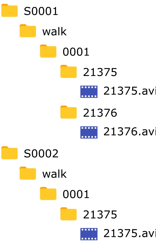
To use this tool, the raw video data must be recorded using the Sony RX0 II camera system, and should be downloaded using the options: Add the Camera Label (prefix) and Do not add the Shooting Date/Time. The raw video files must be accompanied by a data spec .csv file, which can have any name, however it must be the only .csv file within the directory alongside the video files. The data spec .csv file must have a header row of: Trial,SubjectId,Type,Action,CalibrationId. Each subsequent row should contain the relevant information under each header column that corresponds to the trial.
For example, a data collection consisting of the following recordings in this order:
subject 1, walk
subject 1, run
subject 2, walk
subject 2, run
would require a data spec .csv as follows:
If your video data and .csv file meet these requirements, you can use the Format Sony Multicam tool by clicking on the tool in the dropdown. A dialog with these requirements must be acknowledged, as shown below.
When prompted, select the directory containing your raw video files and .csv file, which will be organized into a data structure meeting the Theia3D specification. Continuing with the above example dataset, the resulting data structure would be:
After successful formatting of the data, an additional file changelog.csv is created which documents the mapping of raw video files to the organized file structure.
Object calibration is performed in order to determine the position and orientation of all cameras in the system in 3D space using a recorded object calibration trials. See Recording Extrinsic Object Calibrations for detailed instructions for recording object calibration trials.
Load video files (.mp4 or .avi) containing the extrinsic calibration object. To load the videos, browse to and select the folder containing the videos. The structure of this folder must conform to the format described in Video Data.
Detects and indicates the camera manufacturer based on the videos loaded. This allows the automatic application of default Sony RX0 II camera intrinsic parameters when the calibration videos were recorded using this camera system (see below).
Load default lens calibration parameters for Sony RX0 II cameras and apply them to all cameras. This can be used to avoid performing a lens calibration when using the RX0 II cameras. Loading default intrinsics overwrites any existing lens calibration parameters. Note: These parameters are only valid for Sony RX0 II cameras with standard lenses. For any other cameras or lenses these default parameters are invalid.
Load a .txt file defining the calibration object. Each line of the file contains comma-separated x-y-z coordinates of one of the key points on the object in mm. To load the object, browse to and select the object file. Once loaded, the object points will be displayed in the table.
A minimum of 6 points per camera is required to calibrate the system using object calibration
Save the current object definition. To save the object, browse to the desired save location and enter the desired filename.
Add a calibration object point definition (x, y, z coordinate values).
Add a calibration object point definition (x, y, z coordinate values).
If checked, the selected object point will advance each time a point is identified in one of the 2D views.
The ID of the camera corresponding to the current 2D view. Use the drop-down to select a different 2D view. Maximizing a view will automatically select it.
Remove the currently selected point from the current view.
Remove all points from the current view.
Remove all points from all views.
Perform the extrinsic calibration for all of the cameras. After performing the calibration, the position of any camera points that were not identified before the calibration are calculated and drawn in the 2D views as an ‘*’.
As with the method, the results dialog window provides the options to Save, Save & Assign, or to acknowledge and close the results dialog window using Ok.
When using the checkerboard extrinsic calibration, sometimes the origin may appear at an undefined location because the board was not recognized in the origin frame. This feature allows you to adjust the reference frame by clicking on an object (typically four squares on the checkerboard). Since the frame is just being adjusted (not computed), a calibration needs to be loaded to use this feature, and the relative pose of the cameras will be unchanged. Note: To adjust the origin, you need to manually identify the object points for three cameras only.
The Organize Videos tool converts a folder of videos into a structure that can be used by Theia3D. This functionality is useful when collecting large data sets.
The Basic tab is the best option when organizing videos that have user-defined file names, such as those collected using OptiTrack, Qualisys, or Vicon camera systems. To use this feature, the video files must be named using the following reserved terms, separated by underscores or periods:
Cam ID: (Required) The ID of the camera corresponding to the video file. This must be the same ID as in the calibration file.
Subject: (Recommended) Unique subject identifier (i.e. sub001).
Action: (Recommended) The action the subject is performing (i.e. walk).
Trial: (Recommended) The trial number (i.e. 001 or walk01).
Acceptable delimiters include space (' '), hyphen (-), underscore (_), period (.), or space and underscore (' ' and _). Delimiters that should not be used include comma (,) and semi-colon (;).
To format the videos, select the delimiter used in the file name and then select the folder containing the videos using the Browse button. When the directory is selected the dialog will parse the name of a sample file. Note that the delimiter can be changed after the folder is selected and the sample file name will be re-parsed. Use the drop down boxes to indicate the reserved term that each part of the filename corresponds to. Click Format Data to convert the folder to the required structure. The hierachy of the created directory is Subject > Action > Trial > Cam ID. Cam ID is the only reserved term that must be included in the filename; however, it is recommended to include as many of the other reserved terms as possible.
For example, consider a folder with the following video names:
S0001_Walk_001_8_21375.avi
S0001_Walk_001_8_21376.avi
S0002_Walk_001_8_21375.avi
To format these videos, the reserved terms selected are: Subject, Action, Trial, N/A, and Cam ID. The data structure after formatting is:
The Advanced tab is the best option when organizing videos that do not have user-defined file names, such as those collected using Sony RX0 II camera systems. To use this feature, the names of the video files must end with camid_trialid, where camid is the ID of the camera that recorded the video and trialid is a unique identifier for the trial.
To format the videos, select the folder containing the videos using the Browse button. The trial grid is then created with one row for each trial. The File column of each row is filled with the trialid for that trial.
Use the Load Subject and Action Assignments button to load the subject and action IDs for each of the trials from a csv file. Each row of the csv file must contain the trialid, subjectid, and actionid of a single trial, in that order, separated by commas. For example, the csv file used to assign the subject and action IDs in the above figure was:
Press the Format Data button to format the videos in the required folder structure.
Subject and action IDs can also be manually assigned to the trials without using a csv file.
Use the Build Subjects button to open another dialog and create the subject IDs for the trials. A list of previously saved subject IDs can also be loaded and the current list of subjects can be saved using this dialog. Press the Accept button and close the dialog when the subject list is complete. To assign a subject ID to the trials, select the subject ID from the dropdown menu and press the Add button. Select the trials corresponding to the subject from the trial grid (multi-select is possible using Ctrl or Shift modifiers and by click-and-drag) and press the Finish button.
Use the Build Actions button to open another dialog and create the action IDs for the trials. A list of previously saved action IDs can also be loaded and the current list of actions can be saved using this dialog. Press the Accept button and close the dialog when the actions list is complete. To assign an action ID to the trials, select the action ID from the dropdown menu and press the Add button. Select the trials corresponding to the action from the trial grid (multi-select is possible using Ctrl or Shift modifiers and by click-and-drag) and press the Finish button.
Press the Format Data button to format the videos in the required folder structure.
There are several reasons why the projected 3D skeleton or body segments may appear to be incorrect when reviewing a processed movement trial:
The Smoothing Frequency is too low for the movement. If the Smoothing Frequency is set too low for the movement contained in the videos, the filtered pose may be underfitting the movement and can cause the skeleton to be momentarily incorrect relative to the videos. This can show up as excessively smooth skeleton movements that do not fully capture the movements in the videos.
The intrinsic lens calibration is inadequate. If the intrinsic lens calibration of your cameras provides relatively low coverage of the camera views or insufficient variation in chessboard angle during the lens calibration trial, it may not adequately adjust for lens distortion or other lens effects. This can result in non-linearities in the camera view(s), which can manifest as warping of the image around the outside of the camera view(s). If the skeleton is momentarily incorrect when the subject approaches the edges of one or more camera views, and/or the skeleton tracking gets worse the closer they are to the border of the camera view, then an inadequate lens calibration may be the cause.
The extrinsic chessboard calibration is inadequate. If the extrinsic calibration of your cameras has relatively high calibration error metrics (RMSE Diagonal, RMSE Angle), it may not provide reliable 3D reconstruction of predicted key points from the 2D camera views. This can result in the projected skeleton ‘drifting’ away from the participant as they move away from the calibrated capture volume origin. This drift can be further exacerbated by inadequate intrinsic lens calibration, which may further reduce the accuracy of the 3D projection when the subject nears the edges of the camera view(s). If the skeleton is momentarily incorrect when the subject moves away from the calibrated capture volume origin, an inadequate extrinsic calibration and/or intrinsic calibration may be the cause(s).
The participant’s body is not sufficiently visible for reliable construction. If the participant being tracked is momentarily occluded or contorted in such a way as to significantly reduce the visibility of one or more body segments, the keypoint detections and projected 3D reconstruction can become temporarily incorrect. This generally manifests as obviously incorrect reconstruction of the participant’s skeleton such as impossible body segment poses or movements, but it can also appear as believable movements that visibly disagree with the videos. If the momentarily incorrect body segment(s) are not clearly visible in three or more camera views when the tracking is incorrect, the visibility (or lack thereof) of the body segment may be the cause.
(OptiTrack Prime Color cameras) Frames dropped by the camera hardware were filled in using Dropped Frames: Last Frame. If there were any camera hardware issues that led to video frames being dropped during the recording of the trial, and the export setting Dropped Frames: Last Frames was used, the videos from cameras with dropped frames will have repeated identical frames for some duration of the video. That is, some videos may show the scene as perfectly stationary while the videos from other cameras that did not suffer dropped frames continue showing the movement. In this case, the person is usually tracked accurately based on the cameras without dropped frames, but the 3D reconstruction of the person’s movement will not align with the person in the videos with dropped frames. This is not incorrect tracking, but rather demonstrates the movement was tracked properly despite the videos showing the person at different instances in time.
Some possible solutions to momentarily incorrect skeleton tracking are as follows:
Increase the Smoothing Frequency. If the skeleton movement appears excessively smooth and is not fully capturing the movements in the video, try increasing the Smoothing Frequency to reduce the effect of the filter and allow the movement to be tracked more accurately. After adjusting the Smoothing Frequency in the you only need to run the analysis step to view the updated pose results.
Reprocess the lens and chessboard calibration trials. If the cause of the issue was an inadequate lens or chessboard calibration, the best approach is to reprocess both calibrations in an effort to improve their results. Reprocess the lens calibration trial before reprocessing the chessboard calibration. Try using the tool to improve the brightness, contrast, or white balance of the videos, or decreasing the Frame Grab Step value to increase the number of frames used to calibrate the lenses and camera system. After reprocessing the lens and chessboard calibrations, reprocess the movement.
Record a new chessboard calibration trial.
Each Sony RX0 II camera includes the following:
Camera (1)
Rechargeable Battery Pack (1)
Micro USB Cable (1)
AC Adaptor (1)
Wrist Strap (1)
Memory Card Protector (1)
Startup Guide (1)
Reference Guide (1)
A Video Speed Class V60 microSD card that exceeds the Class 10 requirement of the cameras and provides increased download speeds.
Each Sony Camera Control Box includes the following:
Camera Control Box (1)
Multi Terminal Connecting Cable - Short (1)
Multi Terminal Connecting Cable - Long (1)
Micro USB Cable (1)
16-Port Gigabit Switch (with power over ethernet)
The switch provides 1 Gbps connections for each of the cameras and a 10 Gbps connection to the collection computer. When connected to a 10 Gbps NIC card in the collection computer, this provides increased download speeds from the cameras.
Power Cord
6ft Cat6 Ethernet Cord (1)
50ft Cat6 Ethernet Cord (1 per camera)
Gigabit PoE Splitter (1 per camera)
Male-to-Male 1/4” Thumb Screw (1 per camera)
Rubber Washer (1 per camera)
The assign calibration file tool is used to copy and nest an extrinsic calibration file within individual trial folders, one level above the video files. This is best practice for storing calibration files with their associated movement trials, and is a requirement for running batch analyses.
Use the Browse button to navigate to and select your extrinsic calibration .txt file.
Plus
Use the plus button to add trials to the Trials list by selecting a folder containing movement trials. All trials within the selected folder will be added to the Trials list, regardless of their depth within the selected folder.
Minus
Use the minus button to remove currently selected trials from the Trials list. Use shift+click or ctrl+click to select groups or individual trials to remove from the Trials list.
Assign the calibration file to only the currently selected files within the Trials list.
Close the Assign Calibration Files tool without assigning any calibration files.
Assign the calibration file to the trials in the Trials list or only the currently selected trials if Just Add to Selection is selected.
The Analysis preferences pane contains advanced options and parameters for adjusting how the movement is analyzed, including subject identification and person tracking, model parameters, and 3D reconstruction parameters.
First and last frame to analyze (inclusive). Modified frame range values are included when preferences are saved. (Default: full trial length)
Intrinsic lens calibration is performed using a calibration chessboard and is used to determine parameters associated with the camera lenses and to correct for distortion and other visual effects. Lens calibration is required for OptiTrack Prime Color camera users, and may be required for Qualisys and Vicon camera users who are not using those third parties’ wand calibration procedures. See for detailed instructions for recording lens calibration trials.
If your lens calibration trial videos require enhancement to improve the brightness, contrast, or white balance, you can use the tool. Use the lens calibration Load Videos button, then open and use the Enhance Videos tool to modify your videos.
Cable Protector (1)
Instruction Manual (1)
Reference Guide (1)
Record a new lens calibration trial. If the results of the lens calibration trial are relatively low and you have tried enhancing the videos and adjusting the Frame Grab Step, you may need to record a new lens calibration trial. This necessitates removing the cameras from the capture volume, and is therefore a more significant undertaking that will also require a new chessboard to be recorded after the cameras are returned to their setup.


Movement data for tracked people from a processed trial can also be exported to .json file format for more open-ended use in scripting environments and as an easily readable file output format. Use the Save Skeleton Poses button to save .json output files, or navigate to Save Skeleton Poses under the File Menu.
Output .json files contain:
Theia3D version number, engines, and kinematic model information
Trial frame rate
Preferences used during process, such as start/end frame, max people, smoothing frequency, etc.
Tracking data for each tracked individual, including ID number, segment names and 4x4 pose matrices, and parameters such as segment length.
subject 3, walk
subject 3, run


Trial,SubjectId,Type,Action,CalibrationId
1,N/A,Calibration,N/A,N/A
2,S0001,Motion,Walk,1
3,S0001,Motion,Run,1
4,S0002,Motion,Walk,1
5,S0002,Motion,Run,1
6,N/A,Calibration,N/A,N/A
7,S0003,Motion,Walk,2
8,S0003,Motion,Run,2/Chessboard
/Calibration
/001
/[cam ID folders]
/…
/002
/…
/S0001
/Walk
/001
/…
/Run
/001
/…
/S0002
/Walk
/001
/…
/Run
/001
/…
/S0003
/Walk
/001
/…
/Run
/001
/…Calibration - Commands to check or process calibrations.
Tools - Commands to enhance, organize, and modify data.
Settings - Access Theia3D preferences dialog.
Help - Access help and program information.

N/A: (Optional) Additional terms in the filename not used by Theia3D.


Image exclusion border size. Image matte area is displayed as a grey border around the camera views when active. The greyed-out portions of the videos will not be used when running the analysis, allowing poorly calibrated image borders to be ignored. Image matte area is not applied during lens calibration.
Maximum number of people to track. (Default: No max)
Select the method for determining person tracking priority. Run Analysis (without 2D) must be performed in order to update person tracking.
Most Visible: Person identification and tracking performed by prioritizing people who are visible in >75% of the total frames from all cameras throughout the entire trial, and ordering them by their distance to the global coordinate system origin.
Closest to Origin: Person identification and tracking performed by ordering all people by their minimum distance to the global coordinate system origin throughout the entire trial. For example, if a person walks directly over the origin, they will likely be identified as person 0.
Order of Appearance: Person identification and tracking performed by numbering people in order of appearance within the capture volume.
Remove any person IDs that are missing for 100 consecutive frames or more. This allows a person who is tracked repeatedly within a single trial (e.g. during several passes into and out of the volume) to be tracked and therefore exported separately, for instance as multiple separate c3d files.
Improve tracking of rotating and non-upright people at the expense of speed. (Default: Off)
If not selected, the generic model will be scaled during Solve Skeleton. If selected, a previously saved model can be used by the inverse kinematics algorithm. Use the Use Saved Model button on the next line to select the model to be used. Note that this option is only available when Max People is 1. (Default: Off)
Uses a larger grid for lens distortion correction. Only use if there is a lot of distortion and loading is slow. (Default: Off)
Uses separated IK chains for the lower body (pelvis and legs) and upper body (torso, arms, and head). No abdomen or neck segments. Shoulder joints and head segment are allowed 6 degrees of freedom. See Default Model Description for a detailed description of this model.
Uses a single, whole-body IK chain including pelvis, abdomen, and thorax segments. See Full Body Model Description for a detailed description of this model. Must be used if saving skeleton poses using FBX format.
Uses separated IK chains for the lower body (pelvis and legs), torso, arms, and head segments. No abdomen or neck segments. Shoulder joints and head segment are allowed 6 degrees of freedom. See Separate Arm and Head Model Description for a detailed description of this model.
If selected, the model used by the inverse kinematics algorithm will have three degrees of freedom at the knee (flexion/extension, ab/adduction, and internal/external rotation). If not selected, the model will have two degrees of freedom at the knee (flexion/extension and ab/adduction). (Default: Off)
Cutoff frequency of the GCVSPL lowpass filter used to smooth the pose from the inverse kinematics. (Default: 20Hz)
Enables the 3D Analysis Bounding Box for use, which restricts person tracking to within a specified 3D volume. This allows people who are visible but not of interested to be ignored, such as the experimenter or other observers. Run Analysis (without 2D) must be performed in order to update person tracking and skeleton visibility.
The 3D camera locations will be used to establish the edges of the analysis bounding box, rather than the x, y, and z origin positions and length, width, and height dimension definitions.
Origin X: Position of the center of the bounding box along the global coordinate system X-axis.
Origin Y: Position of the center of the bounding box along the global coordinate system Y-axis.
Origin Z: Position of the center of the bounding box along the global coordinate system Z-axis. Minimum value is half the bounding box height.
Length: Bounding box dimension along the global coordinate system X-axis.
Width: Bounding box dimension along the global coordinate system Y-axis.
Height: Bounding box dimension along the global coordinate system Z-axis.

Load video files (.mp4 or .avi) containing the intrinsic lens calibration trial. To load the videos, browse to and select the folder containing the videos. The structure of this folder must conform to the format described in Video Data. Note that videos loaded using this dialog are rendered in grayscale.
The step between frames searched for chessboards. Smaller values require longer to process, but may provide improved calibration results compared to larger values.
Use a custom size chessboard for the calibration. Only select this option if not using the chessboard provided by Theia Markerless.
Square Size: The width and height of each square on the chessboard. Measured in mm.
Number of Squares High: The number of inner squares in the vertical direction of the chessboard.
Number of Squares Wide: The number of inner squares in the horizontal direction of the chessboard.
Perform the intrinsic calibration for all of the cameras.
Save the intrinsic calibration parameters in a format that can be loaded during future calibrations. This is useful when the intrinsic parameters do not change between calibrations. To save the intrinsic calibration, browse to the desired save location and enter the desired filename.
Load the intrinsic calibration parameters from a previous calibration. This is useful when the intrinsic parameters do not change between calibrations. To load the intrinsic calibration, browse to and select the previously saved intrinsic lens calibration file.
Merge the intrinsic calibration parameters from the current calibration trial with those from a previous calibration. This is useful when new cameras have been acquired that need to be added to an existing intrinsic calibration file, or if a new intrinsic calibration trial has been recorded for a subset of cameras that are already in an existing intrinsic calibration file and the old camera parameters should be replaced. To add or replace intrinsic parameters for a set of cameras within an existing intrinsic calibration file, load the intrinsic calibration trial for those cameras, select the Frame Grab Step, and click Calibrate Lenses.
After the lenses have been calibrated, click Merge Intrinsics, then navigate to and open the existing intrinsic calibration file to which the new parameters should be merged. A new, merged intrinsic calibration file will be saved next to the existing file.
After the lens calibration is complete, a dialog will appear with the results of the intrinsic lens calibration trial.
The result metrics can be interpreted as follows:
The number of video frames used to calibrate each camera.
The proportion (maximum value 1) of the camera view covered during the intrinsic lens calibration trial. Recommend >0.9 as a quality threshold.
The maximum angle of the chessboard relative to the camera image plane during the intrinsic lens calibration trial. Recommend 30-60 degress as a quality threshold.
After acknowledging the lens calibration results dialog window, the camera views will be updated to visualize the results of the lens calibration process. The green shading is a heatmap of the detected chessboard across the camera view, where the green area indicates the portion of the view that was covered during the calibration and the intensity of the green area indicates the number of frames in which the chessboard was detected while covering that part of the view.

Chessboard calibration is performed in order to determine the position and orientation of all cameras in the system in 3D space using a recorded chessboard calibration trials. See Recording Extrinsic Chessboard Calibrations for detailed instructions for recording chessboard calibration trials.
Load video files (.mp4 or .avi) containing the chessboard calibration trial. To load the videos, browse to and select the folder containing the videos. The structure of this folder must conform to the format described in Video Data.
The step between frames searched for chessboards. Smaller values take longer to process, but may provide slightly improved calibration results compared to larger values.
Detects and indicates the camera manufacturer based on the videos loaded. This allows the automatic application of default Sony RX0 II camera intrinsic parameters when the calibration videos were recorded using this camera system (see below).
Automatically selected after loading videos recorded using a Sony RX0 II camera system. This option should be selected to utilize the built-in intrinsic parameters for the Sony RX0 II cameras. Note: These parameters are only valid for Sony RX0 II cameras with standard lenses. For any other cameras or lenses these default parameters are invalid.
Loads intrinsic lens parameters for the camera views loaded.
Frame to use to set the global coordinate system of the capture volume. If the chessboard is not detected in at least three views in this frame, the closest frame in which it can be detected will be used.
Uses two (instead of the default of three) cameras to locate the origin frame. Use this option if the board is difficult to see in the triangulation frame from three cameras.
Set the coordinate system axis that is defined by the normal axis of the chessboard.
Set the coordinate system axis that is defined by the long axis of the chessboard.
Use a custom size chessboard for the calibration. Only select this option if not using the chessboard provided by Theia Markerless.
Square Size: The width and height of each square on the chessboard. Measured in mm.
Number of Squares High: The number of inner squares in the vertical direction of the chessboard.
Number of Squares Wide: The number of inner squares in the horizontal direction of the chessboard.
Perform the extrinsic calibration for all of the cameras.
After the camera calibration is complete, a dialog will appear with the results of the chessboard calibration trial. The result metrics can be interpreted as follows:
The result metrics can be interpreted as follows:
The number of video frames used to calibrate each camera.
RMSE error of the reprojected 3D chessboard points relative to the detected chessboard points in 2D, for each camera view. Measured in mm. Since this is an error relative to 0 mm for all chessboards regardless of size, a 1 mm RMSE reprojection has the same meaning for all sizes of chessboard.
RMSE Diagonal
RMSE error of the length of the diagonals of the 4 outer corners of the chessboard relative to their known lengths, for all triangulated chessboard detections. Measured in mm. Provides an absolute error measure, not normalized to the size of the chessboard. Therefore, a 1 mm RMSE diagonal for a large board is a smaller percentage error than a 1 mm RMSE diagonal for a small board. Not affected by the number or size of the chessboard squares. Recommend using <1 mm as ‘Excellent’ and <2 mm as ‘Acceptable’; calibrations with RMSE Diagonal above 2 mm are not recommended for use.
RMSE error of the angle of the 4 outer corners of the chessboard relative to their known angle of 90 degrees, for all triangulated chessboard detections. Measured in degrees. Since this is an error relative to 90 degrees for all chessboards regardless of size, a 1 degree RMSE angle has the same meaning for all sizes of chessboard. Not affected by the number or size of the chessboard squares.
RMSE error of the normal distance from each detected chessboard point in 3D to the flat plane formed by the outer four 3D chessboard points. Measured in mm. Provides an absolute error measure, not normalized to the size of the chessboard. Therefore, a 1 mm RMSE flat for a large board indicates a lesser degree of bend in the chessboard than a 1 mm RMSE flat for a small board.
The video frame used to initialize the position and orientation of the global coordinate system.
After reviewing the calibrations results, the folling options are available:
Save allows the calibration to be saved.
Save & Assign initiates two steps:
Opens the Save Calibration window, allowing the calibration to be saved as a .txt file.
Opens the Assign Calibration tool, allowing the previously saved calibration .txt file to be immediately assigned to movement trials.
Ok acknowledges and closes the results dialog window.
After the camera calibration is complete, the calibration trial videos can be reviewed for feedback. The following visual cues projected onto the camera views can be useful in determining which portions of the trial contributed to the calibration, and those that did not. This can be useful for optimizing your calibration trial technique.
The Trials list is populated with all valid trials within the selected batch analysis root folder, once a folder has been selected. Above the trials list are the following options:
Filters trials via string compare and regular expression. Built-in filter options based on trial states can be accessed using the @ symbol, including those shown below.
After searching, the selection box next to ‘Trials’ can be toggled to select or deselect all trials that were returned based on the string search. Helps with batching a subset of the root folder.
Show trial metadata like assigned calibrations, trial length (# frames), and frame rate (FPS).
Right-clicking on any trial within the Trials list will provide the following options:
Open into allows the location of the selected trial data to be opened in Windows Explorer or the command line, as described above in .
Reset Analysis Range will reset the Analysis Frame Range preference to be reset so that the entire trial will be analyzed from the first to last frame of data.
The Trials list has the following features within each row. Right-click on the Trials list header to enable or disable specific details columns as desired.
Dropdown triangle icon that expands to show the processing steps for each trial. Indicates success, warnings, or failures for each step where required.
Selection square that indicates whether the trial is included in the batch analysis. Initially, all trials are selected.
The full path to the trial.
Circle that indicates the status of the trial:
Unknown, or not yet analyzed
Success
Skipped
Already done
Cancelled
Warning
Failed
Icon that indicates the status of the calibration file for the trial
valid structure and calibration file
more than one calibration file was found.
the trial does not have a calibration file.
Filename for the calibration file assigned to the trial. Allows easy distinction when different calibration files should be used for different movement trials within one batch analysis.
Icon that indicates the status of the preferences file for the trial.
default preferences will be used.
custom preferences file will be used.
more than one preferences file was found.
Filename for the preferences file assigned to the trial. Allows easy distinction when different preferences should be used for different movement trials within one batch analysis.
Length of the trial, expressed as the number of frames.
Video frame rate of the trial, expressed as Frames Per Second (FPS).
GCVSPL Cutoff Frequency that will be used to analyze the trial as selected in the preference file for the trial, expressed in Hz. See details below for how to edit the preferences file to change the Cutoff Freq.
List of cameras that will be excluded when processing the trial, based on the list of excluded cameras in the preferences file.
Maximum and minimum 3D corner positions of the tracking bounding box, when applied. Expressed as a set of six values: (min_X, min_Y, min_Z, max_X, max_Y, max_Z), where the minimum corner is located at (origin_X-length/2, origin_Y-width/2, origin_Z-height/2) and the maximum corner is located at (origin_X+length/2, origin_Y+width/2, origin_Z+height/2).
At the bottom of the TMBatch window, the Run Batch button is used to start the batch analysis. After clicking Run Batch, the TMBatch performs a check to identify trials that have already been analyzed. If it finds any, a dialog is shown offering the user to skip or re-run these trials. This allows data to be added to a directory and that directory to be batch processed again without reprocessing completed trials. Once the batch has started, Theia3D will run in the background a full analysis on each checked trial in the list. After the batch has finished, the results of each trial can be viewed in Theia3D by loading the saved workspace belonging to the trial.
The Trials list can be easily modified using to include or exclude groups of trials to allow portions of the trial list to be left out of the batch analysis. This can be useful if you are only interested in analyzing specific portions of your data, for example only analyzing one action. The easiest way to make modifications to the Trials list is using the Search bar above the Trials list in combination with the selection box next at the top of the Trials list, which selects or deselects all currently displayed trials. This can be performed to exclude specific subsets of trials, or include specific subsets of trials from the batch analysis.
An example procedure for using this technique for modifying the Trials list is as follows:
Ensure all trials are currently selected using the ‘select/deselect all’ box at the top of the Trials list.
Use a specific search term in the Search bar to display a subset of trials you wish to exclude.
Confirm the currently displayed trials are those that you wish to exclude.
Use the ‘select/deselect all’ box at the top of the Trials list to deselect these trials.
Note: The list of trials displayed after using the search bar is not the current batch analysis list, but just a list of the trials from within the batch analysis directory that meet the search criteria.
This error message may arise when loading a calibration file exported from Qualisys Track Manager after performing a wand calibration. It indicates that the selected calibration file has inconsistent field of view parameters for the cameras contained within the calibration file. The field of view parameters are important for determining the area of the camera sensor used in the recording of the calibration trial.
The FOV parameters may be inconsistent if the videos for the currently loaded trial were recorded at a camera resolution that differs from that used during the wand calibration. The resolution of the videos must be consistent between the calibration trial and the recorded movement trials.
Perform a new wand calibration using the same camera resolutions as used for your movement trials. If the cameras have not moved since the movement trials were recorded, it may be possible to record and export a new wand calibration file using the same video resolutions as used for the movement trials. This would allow the videos to be calibrated properly.
The extrinsic camera calibration can be checked after the trial has been analyzed fully. For each view, the 2D representation of the skeleton in that view is compared to the 3D skeleton computed from all views. If the alignment can be improved in at least 30% of the frames by translating the entire skeleton within the 2D image for that view, this information is reported in the dialog. You can then choose to deactivate the cameras that are out of calibration and clear the entire analysis.
This command looks for consistent translational offsets between the 2D skeleton detected for a given view and the 3D skeleton projected on that view, even if the translations are small (on the scale of millimeters).
For trials with relatively minimal motion, this may result in views being detected as out of calibration when they are not. If you think you’ve encountered one of these false positives, try checking a trial with more motion that uses the same calibration file. If the trial with increased motion shows similar translational offsets, then the view is likely out of calibration. If you think that a camera may have been moved inadvertently between trials, you can check the calibration of multiple trials to try to determine when the camera was moved.
C0001,Calibration,Chessboard
C0002,S0001,Walk
C0003,S0002,Walk


GPU utilization information


Clear the Search bar.
Confirm that the subset of trials is now deselected within the complete Trials list.
Shortcut: Ctrl + O
Load video files (.mp4 or .avi) for analysis. To load the videos, browse to and select the folder containing the videos. The structure of this folder must conform to the format described in Video Data.
Shortcut: Ctrl + Shift + O
Load the camera calibrations for analysis. To load the calibrations, browse to and select the file containing the calibrations for all of the cameras. The calibration file must conform to the format described in Camera Calibration.
Open a previously saved workspace. To load the workspace, browse to and select the directory containing the workspace.
Shortcut: Ctrl + S
Save the videos, camera calibration, and analysis results in the current workspace to a directory in a format that can be opened by Theia3D. Select the frames to include in the workspace and press the Save button. Browse to the desired save location and enter the name of the directory that will be created to store the workspace files. To overwrite the current workspace, use the dialog to select a .t3d file in the existing workspace folder. Note that this only overwites the results (.t3d and .p3d files) and leaves the videos untouched. In this case, all frames in the workspace must be saved. It is not possible to save to an existing workspace folder other than the currently open one.
Save the current calibration. To save the calibration browse to the desired save location and enter the desired filename.
Save the scaled 3D model. To save the scaled model browse to the desired save location and enter the desired filename. Note that if multiple people are tracked a separate model will be saved for each of them. The files are automatically named as filename_personID.tmb, where personid is automatically assigned.
Shortcut: Ctrl + Shift + S, 1
Save the 3D pose of the tracked people. Select the person (or all people) and the frame range (or select the option to use the analysis frames) to save in the file. Files can be saved in .c3d, .fbx, or .json format. The data included in the files is described in Model Reference.
For .c3d files there is an option to save a multi-subject file. If this option is selected, two .c3d files will be created - one with the unfiltered pose and one with the filtered pose. Both files will contain all tracked subjects. If the multi-subject option is not selected, separate files will be created for each tracked subject.
For .fbx files there is an option to select the exported cooridinate system. Preset options are available for common software programs or custom coordinate system can be defined. Saving an .fbx file requires the full body model to be used when solving the pose.
For .json files the user can select which tracked individuals and which frames of the trial to include in the output file. The .json output files are easily readible in a text editor or used as input for a custom analysis script.
With the desired options selected, press the Save button, browse to the save location and enter the filename. The person ID and filtered tag are appended to the filename as needed.
Opens the pose data for all tracked people in Visual3D. Note: The filtered poses are loaded into Visual3D, and the path to the Visual3D executable must be set correctly in the settings dialog. We strongly recommend an active support agreement for Visual3D, as it is frequently updated to support the latest Theia model changes.
Shortcut: Ctrl + Shift + S, 2
Save each of the 2D view video overlays as an .avi file. The videos saved are identical to the overlays shown in Theia3D; therefore you should modify the options that affect the 2D visualizations in the Display Menu and Settings Menu before saving video overlays. Select the desired frame rate and the frame range (or select the option to use the analysis frames) of the videos and press the Save button. Browse to the desired save location and enter the desired filename. One video file will be saved for each overlay and the files are automatically named as filename_cameraID.avi.
Save the 3D scene as an .avi video file. The video saved is identical to the 3D view shown in the 3D Viewer; therefore you should modify the options that affect the 3D visualizations in the Display Menu and Settings Menu before saving before saving 3D View videos. Select the desired frame rate and the frame range of the videos and press the Save button. Browse to the desired save location and enter the desired filename.


Torso
Lab
Base of neck
Free joint (6 DOF)
Head
Torso
Midpoint of ears
Free joint (6 DOF)
Right Upper Arm
Torso
Right shoulder
Free joint (6 DOF)
Right shoulder
Pelvis
Lab
Midpoint of pelvis plane
Free joint (6 DOF)
Right Thigh
Pelvis
Right hip
Chessboard was successfully detected in 3 or more views for the current video frame, including this particular camera view.
Chessboard was successfully detected in fewer than 3 views for the current video frame, including this particular camera view. This video frame was not used towards the system calibration.
Chessboard was successfully detected in 3 or more views for the current video frame, including this particular camera view, but the reprojection error was too high.
Chessboard was detected, but the blue corner could not be determined in this particular frame from this particular camera view.
3D chessboard points are reprojected onto all 2D camera views for successful calibration frames, including those in which the chessboard is not visible.


The following video provides step-by-step instructions for setting up your Sony RX0 II camera system for the first time. This includes configuring the cameras and control boxes, setting up the multi-camera system, and controlling the system through a web browser.
Remove the camera, battery, memory card protector, and microSD card from the packaging.
Open the battery cover and insert the battery into the camera.
Remove and detach the memory card/connector cover from the camera.
Insert the microSD card into the camera.
Attach the memory card protector to the camera.
Turn the camera on.
Follow the on-screen prompts to set the language, area, date, and time.
Navigate to the in a web browser. Download and install the latest DSC-RX0M2 System Software (Firmware) Update if available. Note that the CCB-WD1 System Software (Firmware) Update is for the camera control boxes, and does not need to be installed in this step.
Set the shoot mode to (Movie) Manual Exposure. This allows you to manually set the Shutter Speed to achieve crisp images without movement blur. Navigate to MENU > Shoot Mode/Drive > Shoot Mode and select (Movie) Manual Exposure.
Turn off audio capture. Navigate to MENU > Movie2 > Audio Recording and select Off.
Set the auto power off temperature to high. Navigate to MENU > Setup1 > Auto Power OFF Temp and select High.
Set the timecode settings. Navigate to MENU > Setup2 > TC/UB Settings > TC Format and select NDF. Navigate to MENU > Setup2 > TC/UB Settings > TC Run and select Free Run. (Note that the NTSC/PAL selector must be set to NTSC for the timecode settings to be available MENU > Setup2 > NTSC/PAL Selector.)
Activate remote control. Navigate to MENU > Setup3 > USB Connection and select PC Remote.
Turn the camera off.
Repeat steps 1-14 for each camera.
Remove the switch and power cord from the packaging.
Connect the power cord to the switch and plug it in.
Remove the 6ft ethernet cord from the packaging.
Connect one end of the ethernet cord to a numbered port on the switch.
Remove the control box, cable protector, short multi-terminal connecting cable, and a gigabit PoE splitter from the packaging.
Remove the back cover from the control box.
Pass the thick end of the multi-terminal cable and the male micro USB and Ethernet branches of the PoE splitter through the cable protector.
Plug the thick end of the multi-terminal cable into the MULTI port on the control box.
Start with a camera and control box, each set up as outlined above.
Remove a male-to-male 1/4” thumbscrew, a rubber washer, and a 50ft ethernet cord from the packaging.
Physically connect the camera to the control box using the thumbscrew and rubber washer. Thread one end of the thumb screw into the hole on the top of the control box. Place the rubber washer over the other end of the thumb screw and thread it into the hole in the bottom of the camera.
Plug the thin end of the multi-terminal cable (the thick end is already connected to the control box) into the MULTI port of the camera.
Navigate to the in a web browser. Download and install the latest CCB-WD1 System Software (Firmware) Update.
With all camera and control box pairs connected to the network switch and the switch connected to the computer, open a web browser on the computer (Google Chrome) and navigate to . If you are having difficulty connecting to the collection webpage you may need to set the TCP/IPv4 properties of the network adapter to automatically obtain an IP address. Navigate to Control Panel > Network and Sharing Center > Change Adapter Settings. Double click on the adapter connected to the network switch. Click Properties, select Internet Protocol Version 4 (TCP/IPv4), and click Properties. Select Obtain IP address automatically and Obtain DNS server address automatically.
The video data for a single trial must be contained in its own folder, and each video file must be in its own subfolder. The name of each subfolder must be the ID of the corresponding camera. There are no requirements on the structure of the names of the video files, but the names must be unique and videos must be .avi or .mp4 format. For example, the figure above shows video data for a walking trial collected using four cameras with IDs 21375, 21379, 21380, and 21381.
Organizing your videos in this format can be achieved using the Organize Videos tool.
It is also best practice to keep the associated extrinsic calibration file nested within the trial folder and beside the camera ID folders. This can be achieved using the tool.
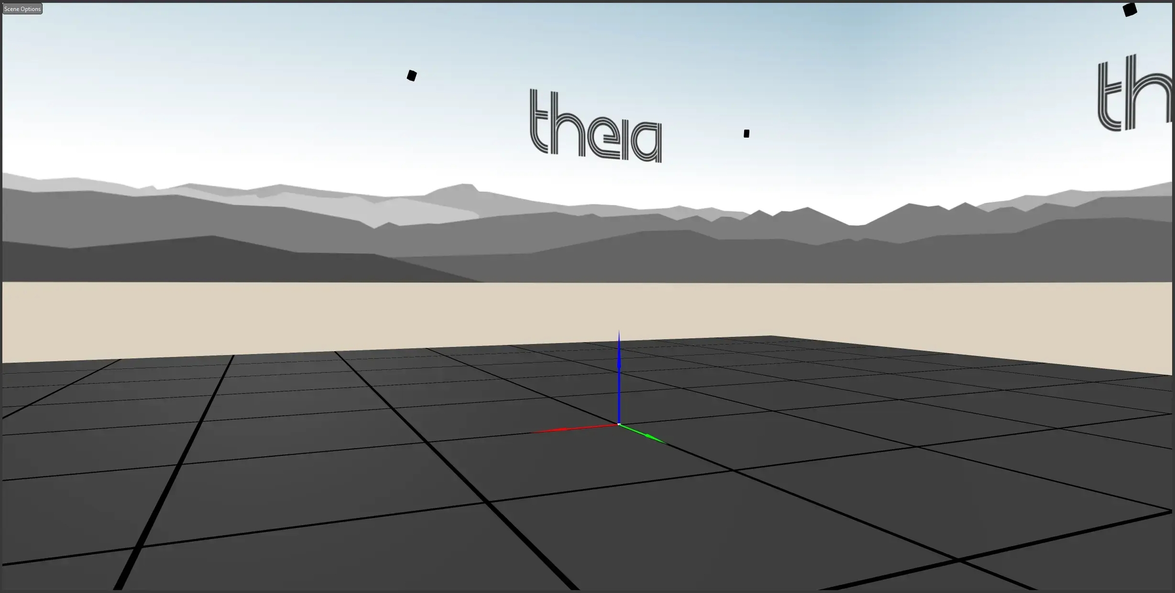
Right elbow
Right Lower Arm
Right Upper Arm
Right elbow
Two rotational DOF (flexion/extension, pronation/supination)
Right elbow
Right wrist
Right Hand
Right Lower Arm
Right wrist
Two rotational DOF (flexion/extension, ad/abduction)
Right wrist
Right mid hand
Left Upper Arm
Torso
Left shoulder
Free joint (6 DOF)
Left shoulder
Left elbow
Left Lower Arm
Left Upper Arm
Left elbow
Two rotational DOF (flexion/extension, pronation/supination)
Left elbow
Left wrist
Left Hand
Left Lower Arm
Left wrist
Two rotational DOF (flexion/extension, ad/abduction)
Left wrist
Left mid hand
Three rotational DOF
Right hip
Right knee
Right Shank
Right Thigh
Right knee
Two rotational degrees of freedom (flexion/extension, ad/abduction) or three rotational degrees of freedom (flexion/extension, ad/abduction, internal/external rotation)
Right knee
Right ankle
Right Foot
Right Shank
Right ankle
Free joint (6 DOF), limited translation
Right ankle
Right mid foot
Right Toes
Right Foot
Right mid foot
One rotational DOF (flexion/extension)
Right mid foot
Right big toe
Left Thigh
Pelvis
Left hip
Three rotational DOF
Left hip
Left knee
Left Shank
Left Thigh
Left knee
Two rotational degrees of freedom (flexion/extension, ad/abduction) or three rotational degrees of freedom (flexion/extension, ad/abduction, internal/external rotation)
Left knee
Left ankle
Left Foot
Left Shank
Left ankle
Free joint (6 DOF), limited translation
Left ankle
Left mid foot
Left Toes
Left Foot
Left mid foot
One rotational DOF (flexion/extension)
Left mid foot
Left big toe
Check that the correct calibration file was selected. The calibration file may be incorrect for the loaded videos. Confirm that you selected the correct calibration file, which should have been generated using a calibration trial from the same data collection session as the loaded movement trial videos.
Check the camera IDs within the calibration file and the loaded video file names. If Organize Videos is performed more than once to organize the video data and different delimiters or different parts of the file names were used to assign ‘Cam ID’, the camera IDs may not match between the calibration file and the loaded videos. If this is the case, the camera ID folder names for the calibration trial and movement trials should be changed to be consistent, and the camera IDs within the calibration file should be modified to match the camera ID folder names.
Check that the number of cameras in the calibration file matches the number of videos loaded. The number of camera views loaded in Theia3D and the number of cameras contained within the calibration file may not match. If the number of camera views loaded in Theia3D does not match the number of cameras listed in the calibration file, double check that you have selected the correct calibration file, that you are not missing any camera views from your loaded movement trial, and that the calibration file has not been modified.


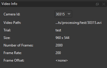
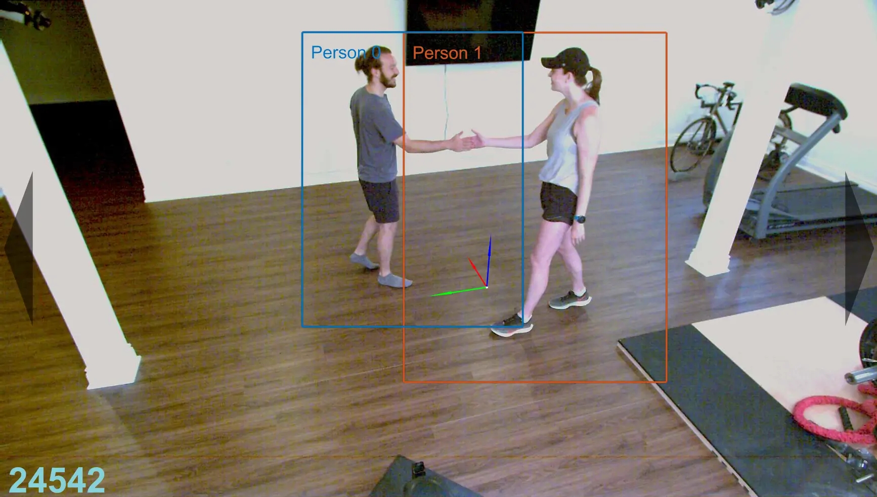
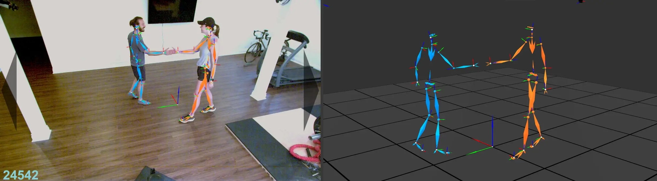
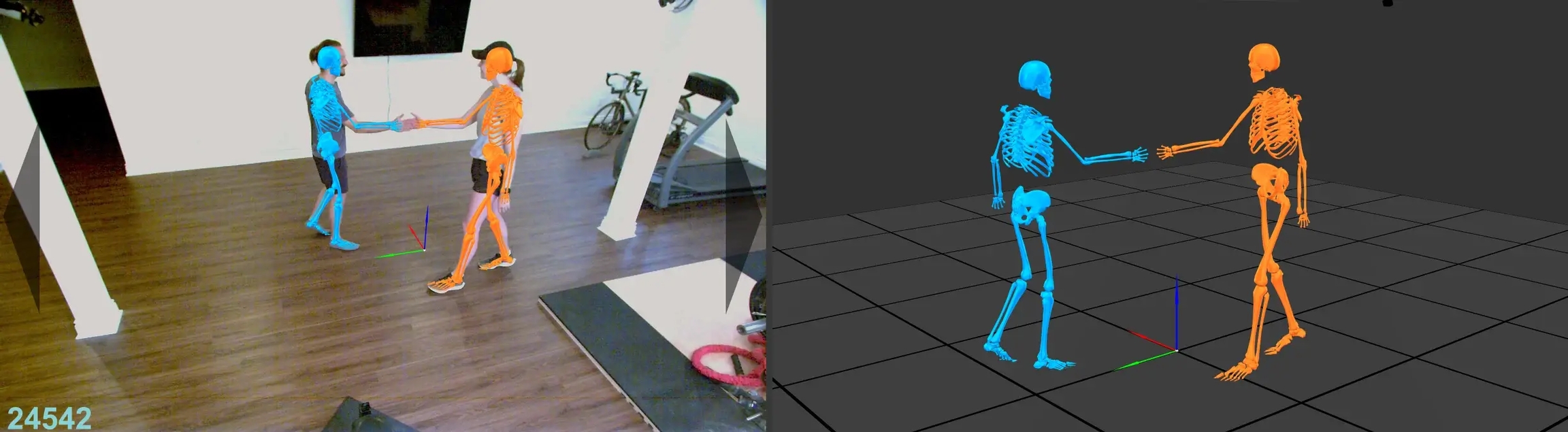
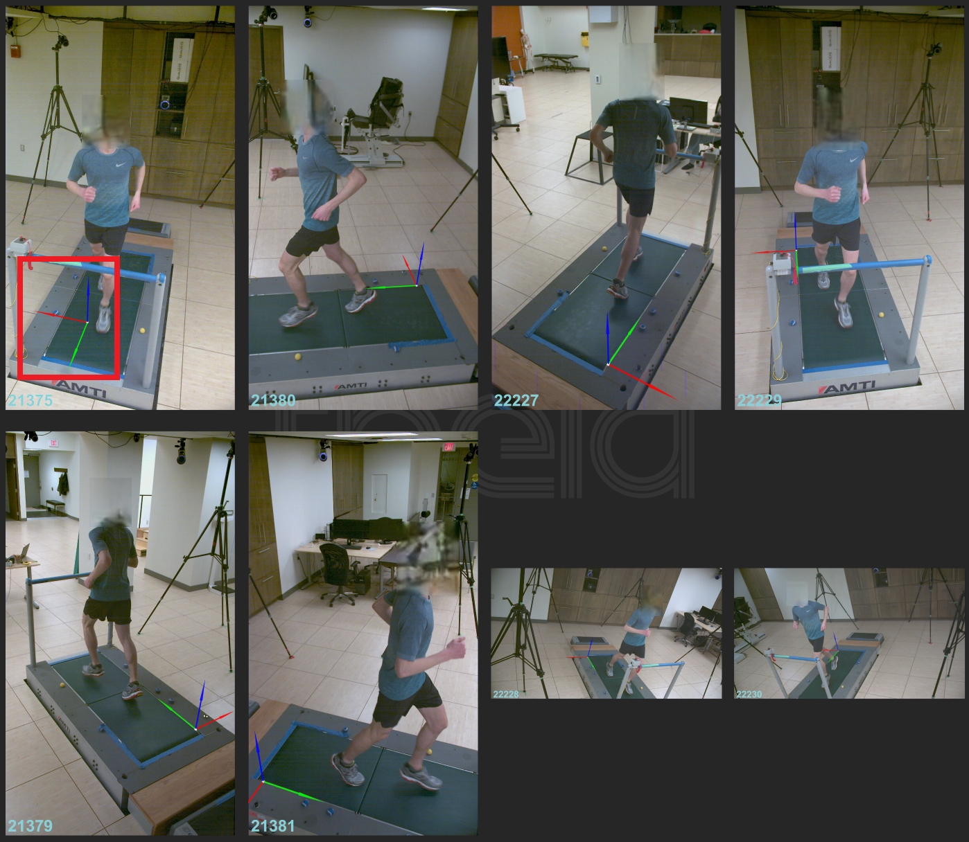
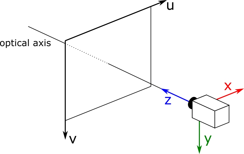
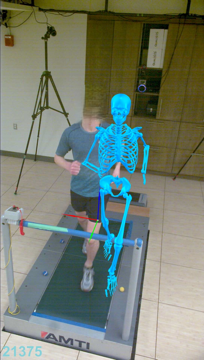
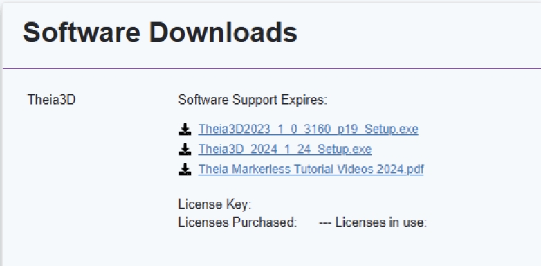
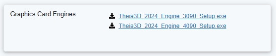
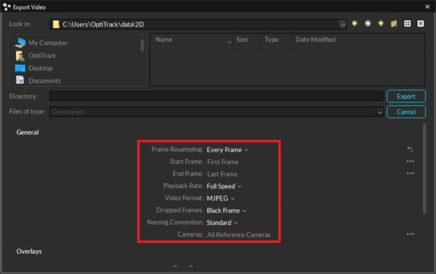
Connect the other end of the ethernet cord to an ethernet port in a dedicated network card in your computer.
Plug the male micro USB branch of the PoE splitter into the DC IN port on the control box.
Plug the male ethernet branch of the PoE splitter into the data port on the control box.
Attach the cable protector to the control box using its attached thumbscrews.
Set the control box MASTER/CLIENT and ON/OFF switches to CLIENT and OFF respectively.
Repeat steps 1-8 for each control box. One control box is required per camera.
Plug one end of the ethernet cord into the female port of the PoE splitter connected to the control box.
Plug the other end of the ethernet cord into a numbered port on the switch.
Repeat steps 1-6 for each camera and control box pair.
Set the MASTER/CLIENT switch of one of the control boxes to MASTER. All other control boxes must be set to CLIENT.
Set the ON/OFF switch of all control boxes to ON.
Mount the cameras in the collection volume. Note that hardware to mount the cameras (tripods, wall mounts, suction mounts, etc.) is not provided.
Open the Box tab of the Control Area and select Update.
Browse to and select the CCB-WD1 firmware update file (previously downloaded).
Wait for the update to be applied to all selected boxes.
A warning stating that the update failed will be shown for any boxes that are already up to date. If the boxes have already been updated, ignore this warning.
Once the update is complete, open the Camera tab of the Control Area.
With all control boxes selected, turn the cameras on.
With all cameras on and selected, link the date/time of all cameras.
Open the Box tab of the Control Area.
With all cameras/control boxes selected, select Initialize.
Torso
Lab
Base of neck
Free joint (6 DOF)
-
-
Head
Lab
Midpoint of ears
Free joint (6 DOF)
-
-
Right Upper Arm
Lab
Right shoulder
Free joint (6 DOF)
Right shoulder
Right elbow
Right Lower Arm
Right Upper Arm
Right elbow
Left Upper Arm
Lab
Left shoulder
Free joint (6 DOF)
Left shoulder
Left elbow
Left Lower Arm
Left Upper Arm
Left elbow
Pelvis
Lab
Midpoint of pelvis
Free joint (6 DOF)
-
-
Right Thigh
Pelvis
Right hip
The full body kinematic model consists of one kinematic chain comprised of the lower body, upper body, and head, with the pelvis as the root segment. Abdomen and neck segments are included. The Full Body Model must be used in order to save skeleton poses as FBX format.
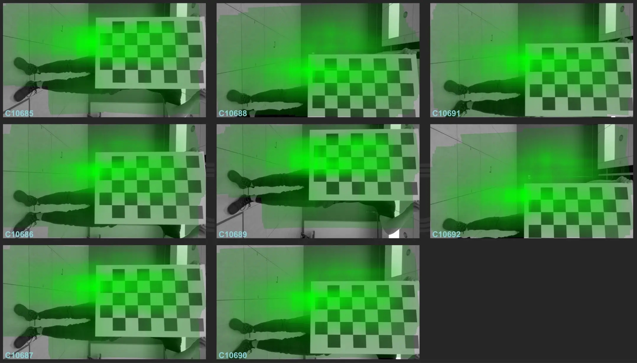
Two rotational DOF (flexion/extension, pronation/supination)
Right elbow
Right wrist
Right Hand
Right Lower Arm
Right wrist
Two rotational DOF (flexion/extension, ad/abduction)
Right wrist
Right mid hand
Two rotational DOF (flexion/extension, pronation/supination)
Left elbow
Left wrist
Left Hand
Left Lower Arm
Left wrist
Two rotational DOF (flexion/extension, ad/abduction)
Left wrist
Left mid hand
Three rotational DOF
Right hip
Right knee
Right Shank
Right Thigh
Right knee
Two or three rotational DOF (flexion/extension, ad/abduction, internal/external rotation)
Right knee
Right ankle
Right Foot
Right Shank
Right ankle
Free joint (6 DOF), limited translation
Right ankle
Right mid foot
Right Toes
Right Foot
Right mid foot
One rotational DOF (flexion/extension)
Right mid foot
Right big toe
Left Thigh
Pelvis
Left hip
Three rotational DOF
Left hip
Left knee
Left Shank
Left Thigh
Left knee
Two or three rotational DOF (flexion/extension, ad/abduction, internal/external rotation)
Left knee
Left ankle
Left Foot
Left Shank
Left ankle
Free joint (6 DOF), limited translation
Left ankle
Left mid foot
Left Toes
Left Foot
Left mid foot
One rotational DOF (flexion/extension)
Left mid foot
Left big toe
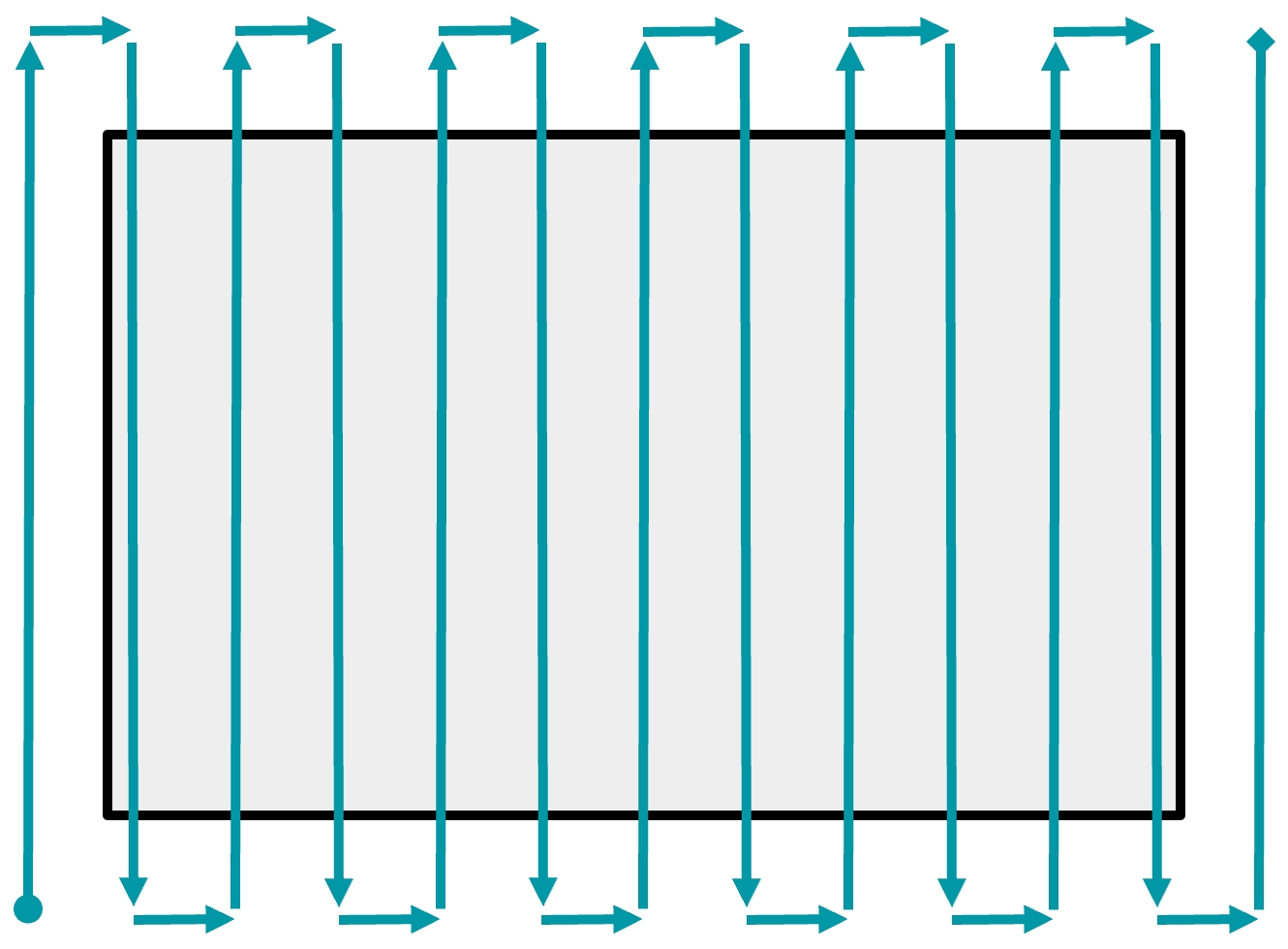
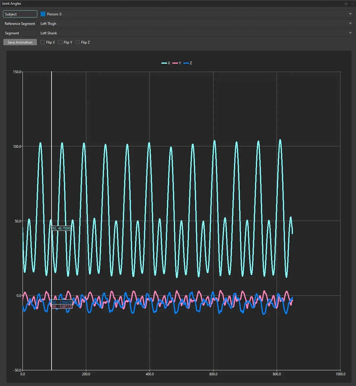
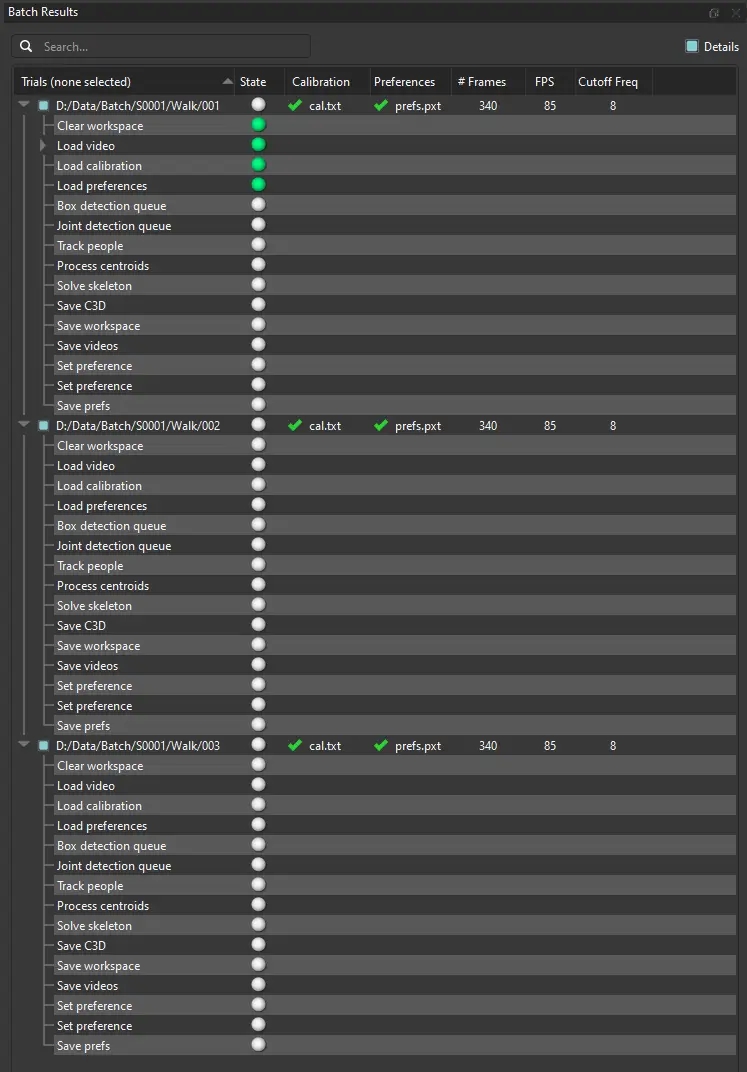
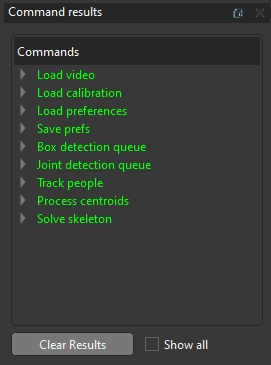
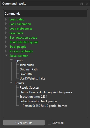
Neck
Torso
Base of neck
Three rotational DOF
Torso
Head
Head
Neck
Midpoint of ears
Three rotational DOF
Neck
-
Right Upper Arm
Torso
Right shoulder
Free joint (6 DOF)
Right shoulder
Right elbow
Right Lower Arm
Right Upper Arm
Right elbow
Two rotational DOF (flexion/extension, pronation/supination)
Right elbow
Right wrist
Right Hand
Right Lower Arm
Right wrist
Two rotational DOF (flexion/extension, ad/abduction)
Right wrist
Right mid hand
Left Upper Arm
Torso
Left shoulder
Free joint (6 DOF)
Left shoulder
Left elbow
Left Lower Arm
Left Upper Arm
Left elbow
Two rotational DOF (flexion/extension, pronation/supination)
Left elbow
Left wrist
Left Hand
Left Lower Arm
Left wrist
Two rotational DOF (flexion/extension, ad/abduction)
Left wrist
Left mid hand
Right Thigh
Pelvis
Right hip
Three rotational DOF
Right hip
Right knee
Right Shank
Right Thigh
Right knee
Two or three rotational DOF (flexion/extension, ad/abduction, internal/external rotation)
Right knee
Right ankle
Right Foot
Right Shank
Right ankle
Free joint (6 DOF), with limited translation
Right ankle
Right mid foot
Right Toes
Right Foot
Right mid foot
One rotational DOF (flexion/extension)
Right mid foot
Right big toe
Left Thigh
Pelvis
Left hip
Three rotational DOF
Left hip
Left knee
Left Shank
Left Thigh
Left knee
Two or three rotational DOF (flexion/extension, ad/abduction, internal/external rotation)
Left knee
Left ankle
Left Foot
Left Shank
Left ankle
Free joint (6 DOF), with limited translation
Left ankle
Left mid foot
Left Toes
Left Foot
Left mid foot
One rotational DOF (flexion/extension)
Left mid foot
Left big toe
Pelvis
Lab
Midpoint of pelvis
Free joint (6 DOF)
-
Abdomen
Abdomen
Pelvis
Pelvis origin
Two rotational DOF (flexion/extension, abduction/adduction)
Pelvis
Torso
Torso
Abdomen
Base of neck
Three rotational DOF, one translational DOF (along Z)
Abdomen
Neck